MDS-E/EH Series Instruction Manual
4 Setup
238
IB-1501229-F
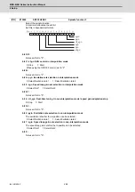
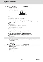
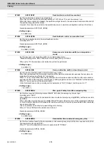
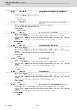
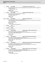
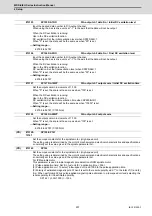
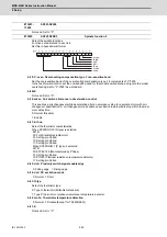
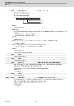
Set the unique constants for the spindle motor. (High-speed coil)
The setting value is determined by the motor's mechanical and electrical characteristics and specifications,
so normally set the value given in the spindle parameter list.
Set the unique constants for the spindle motor. (Low-speed coil)
The setting value is determined by the motor's mechanical and electrical characteristics and specifications,
so normally set the value given in the spindle parameter list.
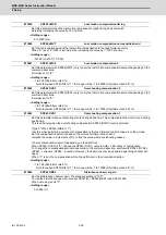
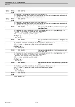
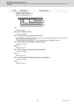
Set the standard output to be displayed as 100% in load meter using the short-time rated output ratio.
To display the continuous rated output as 100%, set as follows.
Continuous rated output/Short-time rated output × 100
When "0" is set, normal display will be applied.
---Setting range---
0 to 100 (%)
Set the base speed of the standard output to be displayed as 100% in load meter.
When "0" is set, the base speed of the short-time rated output will be applied.
---Setting range---
0 to 32767 (r/min)
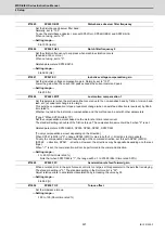
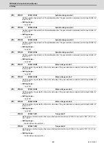
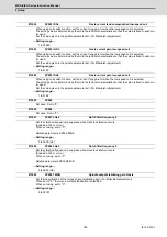
Not used. Set to "0".
(PR)
#13143-
13160
SP143-SP160
(PR)
#13161-
13192
SP161-SP192
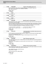
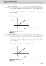
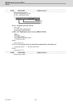
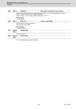
#13193
SP193 LMR
Change magnification for load meter standard output
(High-speed coil)
#13194
SP194 LMN
Base speed for load meter standard output (High-speed
coil)
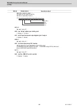
#13195
SP195 LMRL
Change magnification for load meter standard output
(Low-speed coil)
#13196
SP196 LMNL
Base speed for load meter standard output (Low-speed
coil)
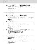
#13197-
13198
SP197-SP198
Summary of Contents for MDS-E
Page 1: ......
Page 3: ......
Page 15: ......
Page 17: ......
Page 19: ......
Page 21: ......
Page 31: ......
Page 32: ...1 IB 1501229 F 1 Installation ...
Page 76: ...45 IB 1501229 F 2 Wiring and Connection ...
Page 132: ...101 IB 1501229 F 3 Safety Function ...
Page 142: ...111 IB 1501229 F 4 Setup ...
Page 277: ...MDS E EH Series Instruction Manual 4 Setup 246 IB 1501229 F ...
Page 278: ...247 IB 1501229 F 5 Servo Adjustment ...
Page 351: ...MDS E EH Series Instruction Manual 5 Servo Adjustment 320 IB 1501229 F ...
Page 352: ...321 IB 1501229 F 6 Spindle Adjustment ...
Page 404: ...373 IB 1501229 F 7 Troubleshooting ...
Page 455: ...MDS E EH Series Instruction Manual 7 Troubleshooting 424 IB 1501229 F ...
Page 456: ...425 IB 1501229 F 8 Maintenance ...
Page 475: ...MDS E EH Series Instruction Manual 8 Maintenance 444 IB 1501229 F ...
Page 476: ...445 IB 1501229 F 9 Power Backup System ...
Page 494: ...463 IB 1501229 F 10 Appx 1 Cable and Connector Assembly ...
Page 504: ...473 IB 1501229 F 11 Appx 2 D A Output Specifications for Drive Unit ...
Page 514: ...483 IB 1501229 F 12 Appx 3 Protection Function ...
Page 523: ...MDS E EH Series Instruction Manual 12 Appx 3 Protection Function 492 IB 1501229 F ...
Page 524: ...493 IB 1501229 F 13 Appx 4 Compliance to EC Directives ...
Page 528: ...497 IB 1501229 F 14 Appx 5 EMC Installation Guidelines ...
Page 540: ...509 IB 1501229 F 15 Appx 6 Higher Harmonic Suppression Measure Guidelines ...
Page 550: ......
Page 554: ......

