


MDS-E/EH Series Instruction Manual
4 Setup
240
IB-1501229-F
Not used. Set to "0".
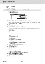
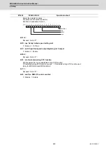
Select the spindle functions.
Functions are allocated to each bit.
Set this in hexadecimal format.
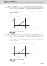
bit F-C: ovsn Overshooting compensation type 3 non-sensitive band
Set the non-sensitive band of the overshooting compensation type 3 in increments of 2°/1000.
In the feed forward control, set the non-sensitive band for the model position droop and ignore the model
overshooting. Set to "2°/1000" as a standard.
bit B-9:
Not used. Set to "0".
bit 8: mken Coil switch allowance in deceleration control
This enables a coil changeover while decelerating after an emergency stop for a spindle motor with coil
changeover specification. A coil changeover may enable an excessive load inertia to stop within the maxi-
mum delay time.
0: Normal (Disable)
1: Enable
bit 7-6: thno
Select the thermistor characteristics.
When SP225/bit3=0 (N type) is selected
bit7,6=
00: For Mitsubishi spindle motor
01: Setting prohibited
10: Setting prohibited
11: Setting prohibited
When SP225/bit3=1 (P type) is selected
bit7,6=
00: KTY84-130 (Manufactured by Philips)
01: Setting prohibited
10: Pt1000 (Platinum resistance temperature detector)
11: Setting prohibited
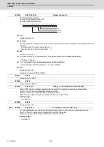
bit 5: ddir Proximity switch signal enable edge
0: Falling edge 1: Rising edge
bit 4: dcd DC excitation mode
0: Normal 1: Start
bit 3: thtyp
Select the thermistor type.
0: Type N thermistor (Mitsubishi standard)
1: Type P thermistor or platinum resistance temperature detector
bit 2: mohn Thermistor temperature detection
0: Normal 1: Disable (Except for TS5690/5691)
bit 1-0:
Not used. Set to "0".
#13201-
13224
SP201-SP224
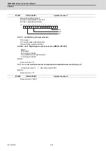
#13225
SP225 SFNC5
Spindle function 5
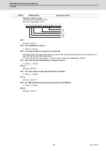
ddir
ovsn
dcd
mohn
mken
thtyp
thno
Summary of Contents for MDS-E
Page 1: ......
Page 3: ......
Page 15: ......
Page 17: ......
Page 19: ......
Page 21: ......
Page 31: ......
Page 32: ...1 IB 1501229 F 1 Installation ...
Page 76: ...45 IB 1501229 F 2 Wiring and Connection ...
Page 132: ...101 IB 1501229 F 3 Safety Function ...
Page 142: ...111 IB 1501229 F 4 Setup ...
Page 277: ...MDS E EH Series Instruction Manual 4 Setup 246 IB 1501229 F ...
Page 278: ...247 IB 1501229 F 5 Servo Adjustment ...
Page 351: ...MDS E EH Series Instruction Manual 5 Servo Adjustment 320 IB 1501229 F ...
Page 352: ...321 IB 1501229 F 6 Spindle Adjustment ...
Page 404: ...373 IB 1501229 F 7 Troubleshooting ...
Page 455: ...MDS E EH Series Instruction Manual 7 Troubleshooting 424 IB 1501229 F ...
Page 456: ...425 IB 1501229 F 8 Maintenance ...
Page 475: ...MDS E EH Series Instruction Manual 8 Maintenance 444 IB 1501229 F ...
Page 476: ...445 IB 1501229 F 9 Power Backup System ...
Page 494: ...463 IB 1501229 F 10 Appx 1 Cable and Connector Assembly ...
Page 504: ...473 IB 1501229 F 11 Appx 2 D A Output Specifications for Drive Unit ...
Page 514: ...483 IB 1501229 F 12 Appx 3 Protection Function ...
Page 523: ...MDS E EH Series Instruction Manual 12 Appx 3 Protection Function 492 IB 1501229 F ...
Page 524: ...493 IB 1501229 F 13 Appx 4 Compliance to EC Directives ...
Page 528: ...497 IB 1501229 F 14 Appx 5 EMC Installation Guidelines ...
Page 540: ...509 IB 1501229 F 15 Appx 6 Higher Harmonic Suppression Measure Guidelines ...
Page 550: ......
Page 554: ......


