

MDS-E/EH Series Instruction Manual
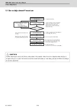
5 Servo Adjustment
254
IB-1501229-F
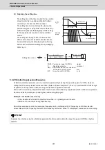
(2) Setting the speed loop lead compensation
The speed loop lead compensation (SV008: VIA) determines the characteristics of the speed loop mainly at low
frequency regions. 1364 is set as a standard, and 1900 is set as a standard during SHG control. The standard value
may drop in respect to loads with a large inertia.
When the VGN1 is set lower than the standard value because the load inertia is large or because machine
resonance occurred, the speed loop control band is lowered. If the standard value is set in the leading
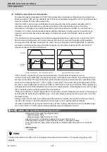
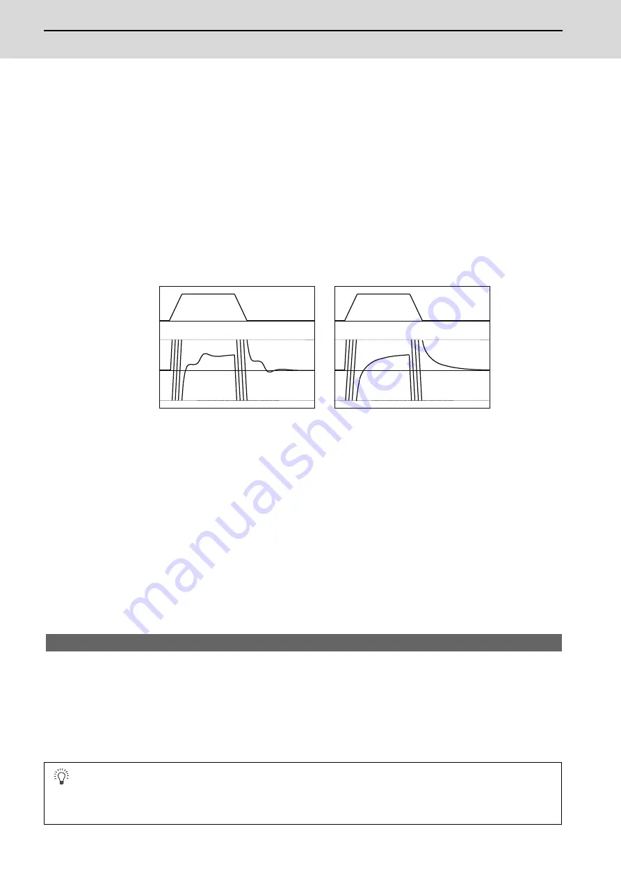
compensation in this status, the leading compensation control itself will induce vibration. In concrete terms, a
vibration of 10 to 20Hz could be caused during acceleration/ deceleration or stopping, and the position droop
waveform could be disturbed when accelerating to a constant speed and when stopped. (Refer to lower left
drawing)
This vibration cannot be suppressed by the vibration suppression functions. Lower the VIA in increments of 100
from the standard setting value. Set a value where vibration does not occur and the position droop waveform
converges smoothly. Because lowering the VIA causes a drop in the position control's trackability, the vibration
suppression is improved even when a disturbance observer is used without lowering the VIA. (Be careful of
machine resonance occurrence at this time.)
If VIA is lowered, the position droop waveform becomes smooth and overshooting does not occur.
However, because the trackability in respect to the position commands becomes worse, the positioning time and
accuracy are sacrificed. VIA must be kept high (set the standard value) to guarantee precision, especially in high-
speed contour cutting (generally F = 1000 or higher). In other words, in a machine aiming for high speed and high
accuracy, a large enough value must be set in VGN1 so that VIA does not need to be lowered. When adjusting, the
cutting precision will be better if adjustment is carried out to a degree where overshooting does not occur and a high
VIA is maintained, without pursuing position droop smoothness.
If there are no vibration or overshooting problems, the high-speed contour cutting precision can be further improved
by setting the VIA higher than the standard value. In this case, adjust by raising the VIA in increments of 100 from
the standard value.
Setting a higher VIA improves the trackability regarding position commands in machines for which cycle time is
important, and the time to when the position droop converges on the in-position width is shortened.
It is easier to adjust the VIA to improve precision and cycle time if a large value (a value near the standard value)
can be set in VGN1, or if VGN1 can be raised equivalently using the disturbance observer.
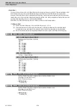
【
#2208
】
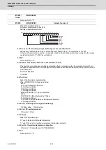
SV008 VIA Speed loop lead compensation
Set the gain of the speed loop integral control.
Standard setting: 1364
Standard setting in the SHG control: 1900
Adjust the value by increasing/decreasing this by about 100 at a time.
Raise this value to improve contour tracking accuracy in high-speed cutting.
Lower this value when the position droop does not stabilize (when the vibration of 10 to 20Hz
occurs).
---Setting range---
1 to 9999
POINT
Position droop vibration of 10Hz or less is not leading compensation control vibration. The position loop gain must be
adjusted.
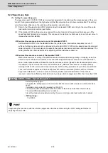
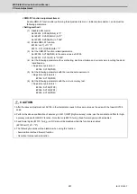
0
0
0
0
Vibration waveform with
lead compensation control
Adjusted position droop waveform
Speed FB
Position
droop
Time
D/A output rang
Time
Time
Time
Summary of Contents for MDS-E
Page 1: ......
Page 3: ......
Page 15: ......
Page 17: ......
Page 19: ......
Page 21: ......
Page 31: ......
Page 32: ...1 IB 1501229 F 1 Installation ...
Page 76: ...45 IB 1501229 F 2 Wiring and Connection ...
Page 132: ...101 IB 1501229 F 3 Safety Function ...
Page 142: ...111 IB 1501229 F 4 Setup ...
Page 277: ...MDS E EH Series Instruction Manual 4 Setup 246 IB 1501229 F ...
Page 278: ...247 IB 1501229 F 5 Servo Adjustment ...
Page 351: ...MDS E EH Series Instruction Manual 5 Servo Adjustment 320 IB 1501229 F ...
Page 352: ...321 IB 1501229 F 6 Spindle Adjustment ...
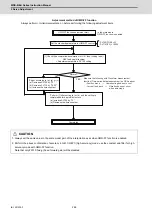
Page 404: ...373 IB 1501229 F 7 Troubleshooting ...
Page 455: ...MDS E EH Series Instruction Manual 7 Troubleshooting 424 IB 1501229 F ...
Page 456: ...425 IB 1501229 F 8 Maintenance ...
Page 475: ...MDS E EH Series Instruction Manual 8 Maintenance 444 IB 1501229 F ...
Page 476: ...445 IB 1501229 F 9 Power Backup System ...
Page 494: ...463 IB 1501229 F 10 Appx 1 Cable and Connector Assembly ...
Page 504: ...473 IB 1501229 F 11 Appx 2 D A Output Specifications for Drive Unit ...
Page 514: ...483 IB 1501229 F 12 Appx 3 Protection Function ...
Page 523: ...MDS E EH Series Instruction Manual 12 Appx 3 Protection Function 492 IB 1501229 F ...
Page 524: ...493 IB 1501229 F 13 Appx 4 Compliance to EC Directives ...
Page 528: ...497 IB 1501229 F 14 Appx 5 EMC Installation Guidelines ...
Page 540: ...509 IB 1501229 F 15 Appx 6 Higher Harmonic Suppression Measure Guidelines ...
Page 550: ......
Page 554: ......


