MDS-E/EH Series Instruction Manual
5 Servo Adjustment
260
IB-1501229-F
【
#2203
】
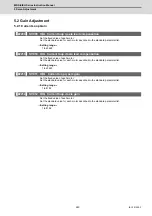
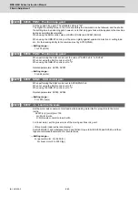
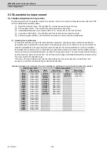
SV003 PGN1 Position loop gain 1
Set the position loop gain. The standard setting is "33".
The higher the setting value is, the more accurately the command can be followed, and the shorter
the settling time in positioning gets, however, note that a bigger shock will be applied to the machine
during acceleration/deceleration.
When using the SHG control, also set SV004 (PGN2) and SV057 (SHGC).
When using the OMR-FF control, set the servo rigidity against quadrant projection or cutting load,
etc. For the tracking ability to the command, set by SV106(PGM).
---Setting range---
1 to 200 (rad/s)
【
#2204
】
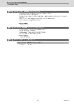
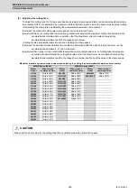
SV004 PGN2 Position loop gain 2
When performing the SHG control, set the value of "SV003 x 8/3" to "SV004".
When not using the SHG control, set to "0".
When using the OMR-FF control, set to "0".
Related parameters: SV003, SV057
---Setting range---
0 to 999 (rad/s)
【
#2257
】
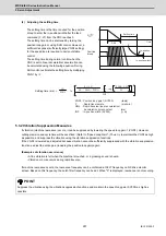
SV057 SHGC SHG control gain
When performing the SHG control, set to SV003(PGN1)×6.
When not using the SHG control, set to "0".
When using the OMR-FF control, set to "0".
Related parameters: SV003, SV004
---Setting range---
0 to 1200 (rad/s)
【
#2237
】
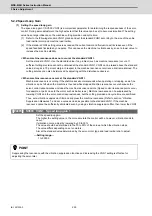
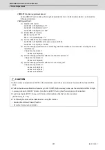
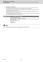
SV037 JL Load inertia scale
Set the motor axis conversion total load inertia including motor itself in proportion to the motor
inertia.
SV037(JL)=(Jm+Jl)/Jm×100
Jm: Motor inertia
Jl: Motor axis conversion load inertia
For linear motor, set the gross mass of the moving sections in kg unit.
<<Drive monitor load inertia ratio display>>
Set SV035/bitF=1 and imbalance torque and friction torque to both SV032 and SV045, and then
repeat acceleration/deceleration for several times.
---Setting range---
For general motor: 0 to 5000 (%)
For linear motor 0 to 5000 (kg)
Summary of Contents for MDS-E
Page 1: ......
Page 3: ......
Page 15: ......
Page 17: ......
Page 19: ......
Page 21: ......
Page 31: ......
Page 32: ...1 IB 1501229 F 1 Installation ...
Page 76: ...45 IB 1501229 F 2 Wiring and Connection ...
Page 132: ...101 IB 1501229 F 3 Safety Function ...
Page 142: ...111 IB 1501229 F 4 Setup ...
Page 277: ...MDS E EH Series Instruction Manual 4 Setup 246 IB 1501229 F ...
Page 278: ...247 IB 1501229 F 5 Servo Adjustment ...
Page 351: ...MDS E EH Series Instruction Manual 5 Servo Adjustment 320 IB 1501229 F ...
Page 352: ...321 IB 1501229 F 6 Spindle Adjustment ...
Page 404: ...373 IB 1501229 F 7 Troubleshooting ...
Page 455: ...MDS E EH Series Instruction Manual 7 Troubleshooting 424 IB 1501229 F ...
Page 456: ...425 IB 1501229 F 8 Maintenance ...
Page 475: ...MDS E EH Series Instruction Manual 8 Maintenance 444 IB 1501229 F ...
Page 476: ...445 IB 1501229 F 9 Power Backup System ...
Page 494: ...463 IB 1501229 F 10 Appx 1 Cable and Connector Assembly ...
Page 504: ...473 IB 1501229 F 11 Appx 2 D A Output Specifications for Drive Unit ...
Page 514: ...483 IB 1501229 F 12 Appx 3 Protection Function ...
Page 523: ...MDS E EH Series Instruction Manual 12 Appx 3 Protection Function 492 IB 1501229 F ...
Page 524: ...493 IB 1501229 F 13 Appx 4 Compliance to EC Directives ...
Page 528: ...497 IB 1501229 F 14 Appx 5 EMC Installation Guidelines ...
Page 540: ...509 IB 1501229 F 15 Appx 6 Higher Harmonic Suppression Measure Guidelines ...
Page 550: ......
Page 554: ......


