MDS-E/EH Series Instruction Manual
5 Servo Adjustment
264
IB-1501229-F
5.3 Characteristics Improvement
5.3.1 Optimal Adjustment of Cycle Time
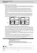
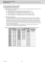
The following items must be adjusted to adjust the cycle time. Refer to the Instruction Manuals provided with each CNC
for the acceleration/deceleration pattern.
[1] Rapid traverse rate (rapid) : This will affect the maximum speed during positioning.
[2] Clamp speed (clamp) : This will affect the maximum speed during cutting.
[3] Acceleration/deceleration time constant (G0t*, G1t*) : Set the time to reach the feedrate.
[4] In-position width (SV024) : This will affect each block's movement command end time.
[5] Position loop gain (SV003) : This will affect each block's movement command settling time.
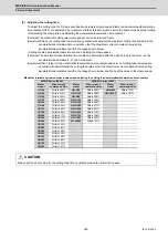
(1) Adjusting the rapid traverse
To adjust the rapid traverse, the CNC axis specification parameter rapid traverse rate (rapid) and acceleration/
deceleration time constant (G0t*) are adjusted. The rapid traverse rate is set so that the motor speed matches the
machine specifications in the range below the maximum speed in the motor specifications. For the acceleration/
deceleration time constants, carry out rapid traverse reciprocation operation, and set so that the maximum current
command value at acceleration/deceleration is within the range shown below. The output torque is limited at areas
near the maximum speed, so monitor the current FB waveform during acceleration/deceleration and adjust so that
the torque is within the specified range.
If the drive unit's input voltage is less than the rated voltage, the torque will easily become insufficient, and
excessive errors will occur easily during acceleration/deceleration.
Maximum tolerable current command value when adjusting the rapid traverse acceleration/deceleration time constant
MDS-E Series (200V)
MDS-EH Series (400V)
Motor
model
Max. current
command value
Motor
model
Max. current
command value
Motor
model
Max. current
command value
HG46
Within 380%
HG-H75
Within 350%
HQ-H903
Within 250%
HG56
Within 390%
HG-H105
Within 270%
HQ-H1103
Within 210%
HG96
Within 260%
HG-H54
Within 420%
HG75
Within 350%
HG-H104
Within 350%
HG105
Within 270%
HG-H154
Within 380%
HG54
Within 420%
HG-H204
Within 310%
HG104
Within 350%
HG-H354
Within 330%
HG154
Within 380%
HG-H453
Within 250%
HG224
Within 310%
HG-H703
Within 240%
HG204
Within 310%
HG-H903
Within 290%
HG354
Within 420%
HG-H1502
Within 190%
HG123
Within 190%
HG223
Within 230%
HG303
Within 240%
HG453
Within 300%
HG703
Within 240%
HG903
Within 290%
HG142
Within 190%
HG302
Within 210%
Summary of Contents for MDS-E
Page 1: ......
Page 3: ......
Page 15: ......
Page 17: ......
Page 19: ......
Page 21: ......
Page 31: ......
Page 32: ...1 IB 1501229 F 1 Installation ...
Page 76: ...45 IB 1501229 F 2 Wiring and Connection ...
Page 132: ...101 IB 1501229 F 3 Safety Function ...
Page 142: ...111 IB 1501229 F 4 Setup ...
Page 277: ...MDS E EH Series Instruction Manual 4 Setup 246 IB 1501229 F ...
Page 278: ...247 IB 1501229 F 5 Servo Adjustment ...
Page 351: ...MDS E EH Series Instruction Manual 5 Servo Adjustment 320 IB 1501229 F ...
Page 352: ...321 IB 1501229 F 6 Spindle Adjustment ...
Page 404: ...373 IB 1501229 F 7 Troubleshooting ...
Page 455: ...MDS E EH Series Instruction Manual 7 Troubleshooting 424 IB 1501229 F ...
Page 456: ...425 IB 1501229 F 8 Maintenance ...
Page 475: ...MDS E EH Series Instruction Manual 8 Maintenance 444 IB 1501229 F ...
Page 476: ...445 IB 1501229 F 9 Power Backup System ...
Page 494: ...463 IB 1501229 F 10 Appx 1 Cable and Connector Assembly ...
Page 504: ...473 IB 1501229 F 11 Appx 2 D A Output Specifications for Drive Unit ...
Page 514: ...483 IB 1501229 F 12 Appx 3 Protection Function ...
Page 523: ...MDS E EH Series Instruction Manual 12 Appx 3 Protection Function 492 IB 1501229 F ...
Page 524: ...493 IB 1501229 F 13 Appx 4 Compliance to EC Directives ...
Page 528: ...497 IB 1501229 F 14 Appx 5 EMC Installation Guidelines ...
Page 540: ...509 IB 1501229 F 15 Appx 6 Higher Harmonic Suppression Measure Guidelines ...
Page 550: ......
Page 554: ......

