MDS-E/EH Series Instruction Manual
5 Servo Adjustment
267
IB-1501229-F
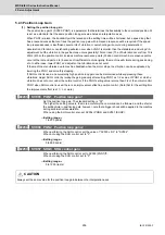
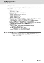
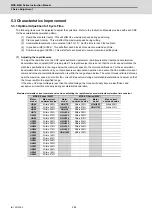
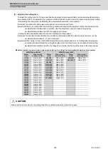
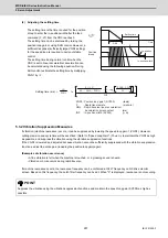
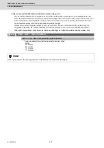
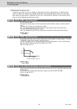
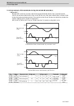
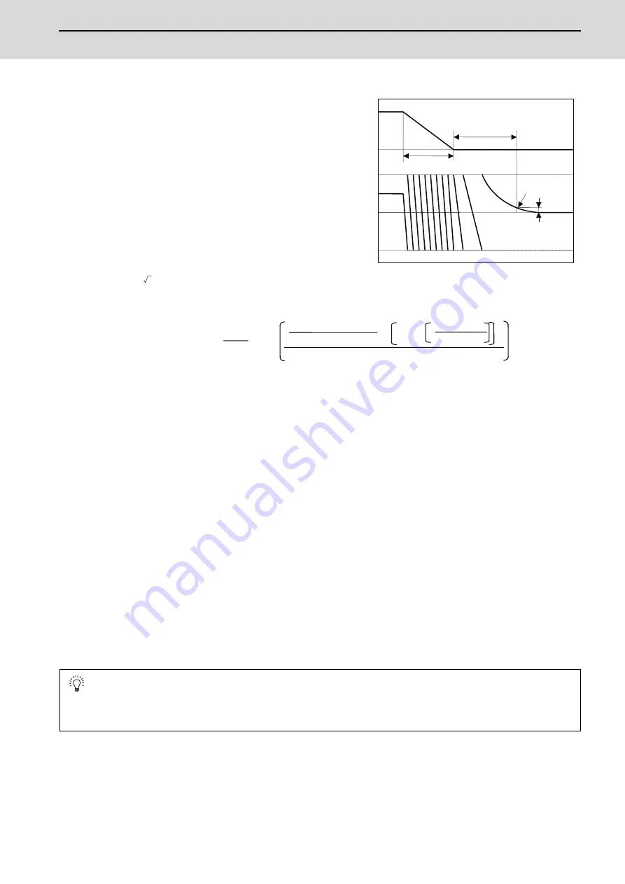
(4) Adjusting the settling time
The settling time is the time required for the position
droop to enter the in-position width after the feed
command (F
Δ
T) from the CNC reaches 0.
The settling time can be shortened by raising the
position loop gain or using SHG control. However, a
sufficient response (sufficiently large VGN1 setting)
for the speed loop is required to carry out stable
control.
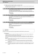
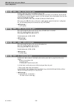
The settling time during normal control when the
CNC is set to linear acceleration/ deceleration can
be calculated using the following equation. During
SHG control, estimate the settling time by multiplying
PGN1 by
.
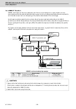
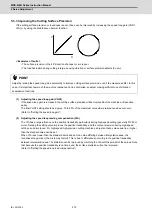
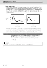
5.3.2 Vibration Suppression Measures
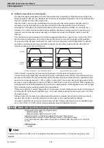
If vibration (machine resonance) occurs, it can be suppressed by lowering the speed loop gain 1 (VGN1). However,
cutting precision and cycle time will be sacrificed. (Refer to "Speed Loop Gain".) Thus, try to maintain the VGN1 as high
as possible, and suppress the vibration using the vibration suppression functions.
If the VGN1 is lowered and adjusted because vibration cannot be sufficiently suppressed with the vibration suppression
functions, adjust the entire gain (including the position loop gain) again.
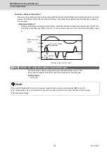
(Examples of vibration occurrence)
• A fine vibration is felt when the machine is touched, or a groaning sound is heard.
• Vibration or noise occurs during rapid traverse.
If machine resonance occurs, the resonance frequency can be confirmed at AFLT frequency on NC drive monitor
screen. Based on this frequency, the notch filter frequency can be set. When "0" is displayed, resonance is not occurring.
POINT
Suppress the vibration using the vibration suppression functions, and maintain the speed loop gain (SV005) as high as
possible.
0
0
F
ԥ
T
Position
droop
F
Time
Setting time
In -position
In -position width
G0tL
2
ln
INP
㧙
F × 10
6
60 × G0tL × PGN1
2
PGN1×G0tL
10
3
1− exp
10
3
PGN1
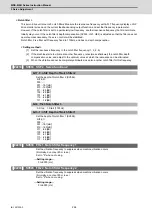
Settling time ( ms)
=
PGN1 : Position loop gain1 (SV003) (rad/s)
F : Rapid traverse rate (mm/min)
G0tL : Rapid traverse linear acceleration/
deceleration time constant (ms)
INP : In-position width (SV024) (
Ǵ
m)
Summary of Contents for MDS-E
Page 1: ......
Page 3: ......
Page 15: ......
Page 17: ......
Page 19: ......
Page 21: ......
Page 31: ......
Page 32: ...1 IB 1501229 F 1 Installation ...
Page 76: ...45 IB 1501229 F 2 Wiring and Connection ...
Page 132: ...101 IB 1501229 F 3 Safety Function ...
Page 142: ...111 IB 1501229 F 4 Setup ...
Page 277: ...MDS E EH Series Instruction Manual 4 Setup 246 IB 1501229 F ...
Page 278: ...247 IB 1501229 F 5 Servo Adjustment ...
Page 351: ...MDS E EH Series Instruction Manual 5 Servo Adjustment 320 IB 1501229 F ...
Page 352: ...321 IB 1501229 F 6 Spindle Adjustment ...
Page 404: ...373 IB 1501229 F 7 Troubleshooting ...
Page 455: ...MDS E EH Series Instruction Manual 7 Troubleshooting 424 IB 1501229 F ...
Page 456: ...425 IB 1501229 F 8 Maintenance ...
Page 475: ...MDS E EH Series Instruction Manual 8 Maintenance 444 IB 1501229 F ...
Page 476: ...445 IB 1501229 F 9 Power Backup System ...
Page 494: ...463 IB 1501229 F 10 Appx 1 Cable and Connector Assembly ...
Page 504: ...473 IB 1501229 F 11 Appx 2 D A Output Specifications for Drive Unit ...
Page 514: ...483 IB 1501229 F 12 Appx 3 Protection Function ...
Page 523: ...MDS E EH Series Instruction Manual 12 Appx 3 Protection Function 492 IB 1501229 F ...
Page 524: ...493 IB 1501229 F 13 Appx 4 Compliance to EC Directives ...
Page 528: ...497 IB 1501229 F 14 Appx 5 EMC Installation Guidelines ...
Page 540: ...509 IB 1501229 F 15 Appx 6 Higher Harmonic Suppression Measure Guidelines ...
Page 550: ......
Page 554: ......


