MDS-E/EH Series Instruction Manual
5 Servo Adjustment
275
IB-1501229-F
【
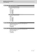
#2205
】
SV005 VGN1 Speed loop gain 1
Set the speed loop gain.
The higher the setting value is, the more accurate the control will be, however, vibration tends to
occur.
If vibration occurs, adjust by lowering by 20 to 30%.
The value should be determined to the 70 to 80% of the value at which the vibration stops.
The value differs depending on servo motors.
Aim at the standard value determined by the servo motor type and load inertia ratio to adjust.
---Setting range---
1 to 30000
【
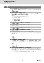
#2208
】
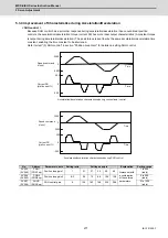
SV008 VIA Speed loop lead compensation
Set the gain of the speed loop integral control.
Standard setting: 1364
Standard setting in the SHG control: 1900
Adjust the value by increasing/decreasing this by about 100 at a time.
Raise this value to improve contour tracking accuracy in high-speed cutting.
Lower this value when the position droop does not stabilize (when the vibration of 10 to 20Hz
occurs).
---Setting range---
1 to 9999
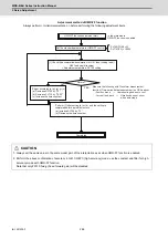
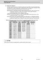
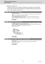
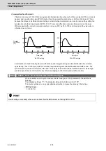
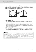
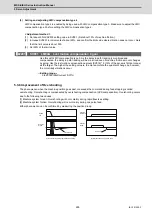
(3) Voltage non-sensitive zone (Td) compensation
With the PWM control of the inverter circuit, a dead time (non-energized time) is set to prevent short-circuits caused
by simultaneous energizing of the P side and N side transistors having the same phase. The dead time has a non-
sensitive zone for particularly low voltage commands. Thus, when feeding with a low speed and a low torque, the
control may be unstable.
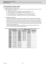
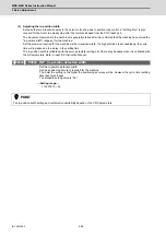
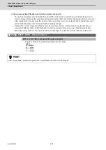
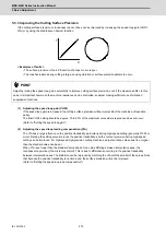
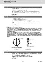
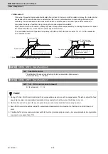
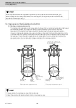
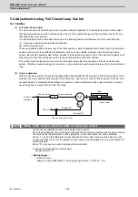
When an unbalanced axis is lowering, the frictional torque and unbalance torque, and the frictional torque and
deceleration torque before the quadrant changes during circle cutting, are balanced. The motor output torque will be
approximately zero, and the control accuracy may drop. In this case, the control accuracy can be improved by using
the voltage non-sensitive band compensation. Note that this may cause vibration to be increased while the motor is
running.
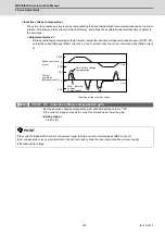
【
#2230
】
SV030 IVC Voltage non-sensitive band compensation
When 100% is set, the voltage reduction amount equivalent to the logical non-energization in the
PWM control will be compensated.
When "0" is set, 100% compensation will be performed.
Adjust in increments of 10% from the default value of 100%.
If increased too much, vibration or vibration noise may be generated.
---Setting range---
0 to 255 (%)
Frictional torque
Lowering
Balanced
Unbalance torque
For unbalance torque
For circle cutting
Cutting direction
Deceleration torque = frictional torque
Motor torque
Ҹ
0
Summary of Contents for MDS-E
Page 1: ......
Page 3: ......
Page 15: ......
Page 17: ......
Page 19: ......
Page 21: ......
Page 31: ......
Page 32: ...1 IB 1501229 F 1 Installation ...
Page 76: ...45 IB 1501229 F 2 Wiring and Connection ...
Page 132: ...101 IB 1501229 F 3 Safety Function ...
Page 142: ...111 IB 1501229 F 4 Setup ...
Page 277: ...MDS E EH Series Instruction Manual 4 Setup 246 IB 1501229 F ...
Page 278: ...247 IB 1501229 F 5 Servo Adjustment ...
Page 351: ...MDS E EH Series Instruction Manual 5 Servo Adjustment 320 IB 1501229 F ...
Page 352: ...321 IB 1501229 F 6 Spindle Adjustment ...
Page 404: ...373 IB 1501229 F 7 Troubleshooting ...
Page 455: ...MDS E EH Series Instruction Manual 7 Troubleshooting 424 IB 1501229 F ...
Page 456: ...425 IB 1501229 F 8 Maintenance ...
Page 475: ...MDS E EH Series Instruction Manual 8 Maintenance 444 IB 1501229 F ...
Page 476: ...445 IB 1501229 F 9 Power Backup System ...
Page 494: ...463 IB 1501229 F 10 Appx 1 Cable and Connector Assembly ...
Page 504: ...473 IB 1501229 F 11 Appx 2 D A Output Specifications for Drive Unit ...
Page 514: ...483 IB 1501229 F 12 Appx 3 Protection Function ...
Page 523: ...MDS E EH Series Instruction Manual 12 Appx 3 Protection Function 492 IB 1501229 F ...
Page 524: ...493 IB 1501229 F 13 Appx 4 Compliance to EC Directives ...
Page 528: ...497 IB 1501229 F 14 Appx 5 EMC Installation Guidelines ...
Page 540: ...509 IB 1501229 F 15 Appx 6 Higher Harmonic Suppression Measure Guidelines ...
Page 550: ......
Page 554: ......


