MDS-E/EH Series Instruction Manual
5 Servo Adjustment
281
IB-1501229-F
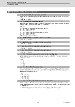
5.3.5 Improvement of Protrusion at Quadrant Changeover
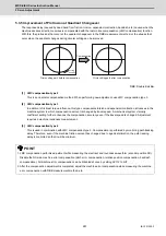
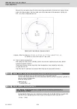
The response delay (caused by dead band from friction, torsion, expansion/contraction, backlash, etc.) caused when the
machine advance direction reverses is compensated with the lost motion compensation (LMC compensation) function.
With this, the protrusions that occur at the quadrant changeover in the DBB measurement method, or the streaks that
occur when the quadrant changes during circular cutting can be improved.
DBB: Double Ball Bar
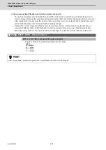
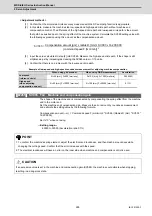
[1] LMC compensation type 2
This is an obsolete compensation method. When performing new adjustment, use LMC compensation type 3.
[2] LMC compensation type 3
In addition to frictional torque influence, this type compensates torsion and expansion/contraction influences in the
machine system in which compensation amount is changed by travel speed. A mechanical system viscosity
coefficient setting further enhances the compensation accuracy even if the travel speed is changed. Adjustment
requires a machine roundness measurement.
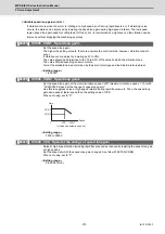
[3] LMC compensation type 4
This is used in combination with LMC compensation type 3. Compensation is performed by monitoring path tracking
delay. Therefore, even if the machine friction amount has changed due to aged deterioration, the path tracking
delay is controlled so that it will be minimum.
POINT
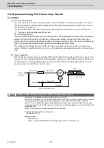
1. LMC compensation performs adjustment while measuring the electrical end roundness waveform (encoder position FB).
Disable the NC side machine error compensation (pitch error compensation, relative position compensation, backlash
compensation). All machine error compensation can be disabled at once by setting SV113 to bit7.
2. After the compensation adjustment is completed, adjust the machine error compensation while measuring the machine
error compensation with DBB measurement method, etc.
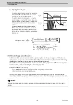
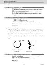
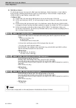
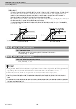
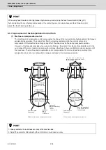
Compensation
Cutting
direction
Circle cutting path after compensation
Circle cutting path before compensation
Summary of Contents for MDS-E
Page 1: ......
Page 3: ......
Page 15: ......
Page 17: ......
Page 19: ......
Page 21: ......
Page 31: ......
Page 32: ...1 IB 1501229 F 1 Installation ...
Page 76: ...45 IB 1501229 F 2 Wiring and Connection ...
Page 132: ...101 IB 1501229 F 3 Safety Function ...
Page 142: ...111 IB 1501229 F 4 Setup ...
Page 277: ...MDS E EH Series Instruction Manual 4 Setup 246 IB 1501229 F ...
Page 278: ...247 IB 1501229 F 5 Servo Adjustment ...
Page 351: ...MDS E EH Series Instruction Manual 5 Servo Adjustment 320 IB 1501229 F ...
Page 352: ...321 IB 1501229 F 6 Spindle Adjustment ...
Page 404: ...373 IB 1501229 F 7 Troubleshooting ...
Page 455: ...MDS E EH Series Instruction Manual 7 Troubleshooting 424 IB 1501229 F ...
Page 456: ...425 IB 1501229 F 8 Maintenance ...
Page 475: ...MDS E EH Series Instruction Manual 8 Maintenance 444 IB 1501229 F ...
Page 476: ...445 IB 1501229 F 9 Power Backup System ...
Page 494: ...463 IB 1501229 F 10 Appx 1 Cable and Connector Assembly ...
Page 504: ...473 IB 1501229 F 11 Appx 2 D A Output Specifications for Drive Unit ...
Page 514: ...483 IB 1501229 F 12 Appx 3 Protection Function ...
Page 523: ...MDS E EH Series Instruction Manual 12 Appx 3 Protection Function 492 IB 1501229 F ...
Page 524: ...493 IB 1501229 F 13 Appx 4 Compliance to EC Directives ...
Page 528: ...497 IB 1501229 F 14 Appx 5 EMC Installation Guidelines ...
Page 540: ...509 IB 1501229 F 15 Appx 6 Higher Harmonic Suppression Measure Guidelines ...
Page 550: ......
Page 554: ......

