MDS-E/EH Series Instruction Manual
5 Servo Adjustment
285
IB-1501229-F
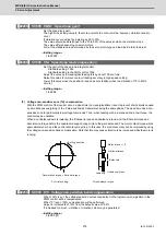
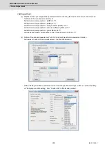
(3) Setting and adjusting LMC compensation type 4
LMC compensation type 4 is enabled by being used with LMC compensation type 3. Make sure to adjust the LMC
compensation type 3 before setting the LMC compensation type 4.
< Adjustment method >
[1] Set about 5-fold SV016 setting value in SV091. (Set about 10% of machine friction.)
[2] Increase SV0091 in increments of about 20%, and confirm the limit value where vibration does not occur. Note
that the limit value is about 500.
[3] Set 50% of the limit value.
【
#2291
】
SV091 LMC4G Lost motion compensation 4 gain
Use this with LMC compensation type 3. As the delay in path tracking is monitored and
compensated, the delay in path tracking will be minimized even if machine friction amount changes
by aging. Use the lost motion compensation amount (SV016) * 5 (10% of the dynamic friction torque)
as the target. The higher the setting value is, the more accurate the quadrant change be; however,
the more likely vibrations occur.
---Setting range---
0 to 20000 (Stall current 0.01%)
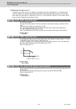
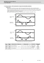
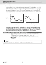
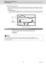
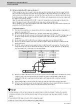
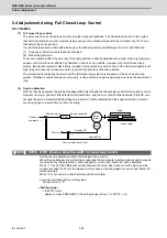
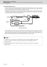
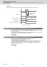
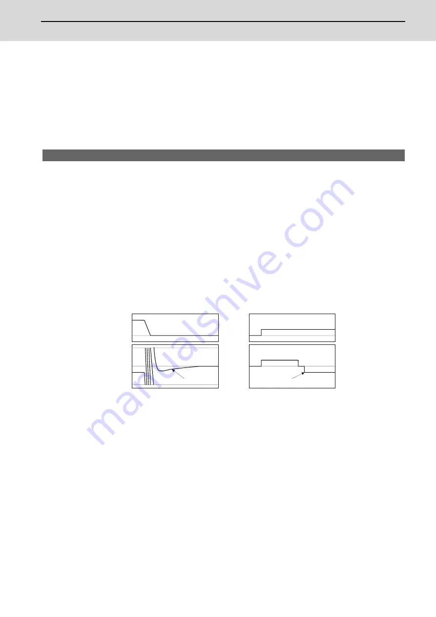
5.3.6 Improvement of Overshooting
The phenomenon when the machine position goes past or exceeds the command during feed stopping is called
overshooting. Overshooting is compensated by overshooting compensation (OVS compensation). Overshooting occurs
due to the following two causes.
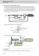
[1] Machine system torsion: Overshooting will occur mainly during rapid traverse settling.
[2] Machine system friction: Overshooting will occur mainly during one pulse feed.
Either phenomenon can be confirmed by measuring the position droop.
0
0
0
0
Position
command
Position
droop
Time
Overshoot
Speed
FB
Position
droop
Time
Overshoot
[1] Overshooting during rapid traverse settling
[2] Overshooting during pulse feed
Summary of Contents for MDS-E
Page 1: ......
Page 3: ......
Page 15: ......
Page 17: ......
Page 19: ......
Page 21: ......
Page 31: ......
Page 32: ...1 IB 1501229 F 1 Installation ...
Page 76: ...45 IB 1501229 F 2 Wiring and Connection ...
Page 132: ...101 IB 1501229 F 3 Safety Function ...
Page 142: ...111 IB 1501229 F 4 Setup ...
Page 277: ...MDS E EH Series Instruction Manual 4 Setup 246 IB 1501229 F ...
Page 278: ...247 IB 1501229 F 5 Servo Adjustment ...
Page 351: ...MDS E EH Series Instruction Manual 5 Servo Adjustment 320 IB 1501229 F ...
Page 352: ...321 IB 1501229 F 6 Spindle Adjustment ...
Page 404: ...373 IB 1501229 F 7 Troubleshooting ...
Page 455: ...MDS E EH Series Instruction Manual 7 Troubleshooting 424 IB 1501229 F ...
Page 456: ...425 IB 1501229 F 8 Maintenance ...
Page 475: ...MDS E EH Series Instruction Manual 8 Maintenance 444 IB 1501229 F ...
Page 476: ...445 IB 1501229 F 9 Power Backup System ...
Page 494: ...463 IB 1501229 F 10 Appx 1 Cable and Connector Assembly ...
Page 504: ...473 IB 1501229 F 11 Appx 2 D A Output Specifications for Drive Unit ...
Page 514: ...483 IB 1501229 F 12 Appx 3 Protection Function ...
Page 523: ...MDS E EH Series Instruction Manual 12 Appx 3 Protection Function 492 IB 1501229 F ...
Page 524: ...493 IB 1501229 F 13 Appx 4 Compliance to EC Directives ...
Page 528: ...497 IB 1501229 F 14 Appx 5 EMC Installation Guidelines ...
Page 540: ...509 IB 1501229 F 15 Appx 6 Higher Harmonic Suppression Measure Guidelines ...
Page 550: ......
Page 554: ......


