


MDS-E/EH Series Instruction Manual
5 Servo Adjustment
288
IB-1501229-F
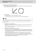
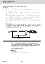
5.3.7 Improvement of the Interpolation Control Path
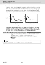
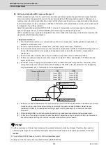
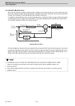
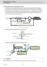
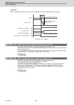
(1) Machine end compensation control
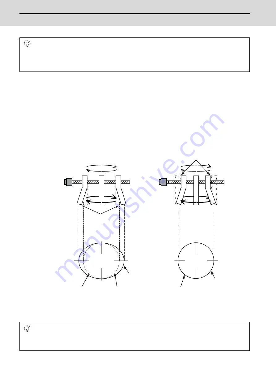
The machine end compensation control compensates the shape of the tool end during high-speed and high-speed
acceleration/deceleration. The spring effect from the machine (spindle) end to the motor (scale) end is
compensated. If the machine has a large spring effect, the shape may be fine during low-speed operation.
However, at high speeds (specially when using a small radius), the section from the machine (spindle) end to the
outer sides of the motor (scale) end could swell, and cause the shape to become elliptical during measurement of
the roundness. The machine end compensation control compensates the motor end position according to the
acceleration size, so the tool end position is always controlled to the commanded position.
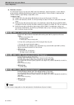
POINT
When using feed forward control (high-speed high-accuracy control), stop the feed forward control (fwd_g=0)
before adjusting the overshooting compensation. If overshooting occurs during subsequent feed forward control,
adjust the feed forward gain (fwd_g).
POINT
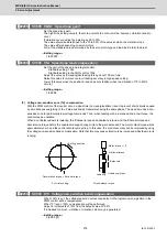
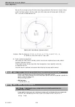
1. Always evaluate the roundness accuracy at the machine side.
2. Adjust the parameter after adjusting the electrical end roundness accuracy.
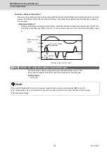
With machine end compensation control
During high acceleration,
the end section swells
outward due to the spring
effect.
The inner side is driven by the
amount that the end section swells
due to the spring effect.
Machine roundness
(machining surface)
Elliptical shape fault
Machine roundness
(machining surface)
Elliptical shape is
improved
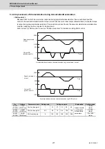
Low speed:
Example:
R25mm
F1000mm/min
High speed
(high acceleration):
Example:
R25mm
F10000mm /min
Both low speed and
high speed are on
the same path.
Command path
(ideal path)
Machine path
(machining surface)
Machine path
(machining surface)
Command path
(ideal path)
Without machine end compensation control
Summary of Contents for MDS-E
Page 1: ......
Page 3: ......
Page 15: ......
Page 17: ......
Page 19: ......
Page 21: ......
Page 31: ......
Page 32: ...1 IB 1501229 F 1 Installation ...
Page 76: ...45 IB 1501229 F 2 Wiring and Connection ...
Page 132: ...101 IB 1501229 F 3 Safety Function ...
Page 142: ...111 IB 1501229 F 4 Setup ...
Page 277: ...MDS E EH Series Instruction Manual 4 Setup 246 IB 1501229 F ...
Page 278: ...247 IB 1501229 F 5 Servo Adjustment ...
Page 351: ...MDS E EH Series Instruction Manual 5 Servo Adjustment 320 IB 1501229 F ...
Page 352: ...321 IB 1501229 F 6 Spindle Adjustment ...
Page 404: ...373 IB 1501229 F 7 Troubleshooting ...
Page 455: ...MDS E EH Series Instruction Manual 7 Troubleshooting 424 IB 1501229 F ...
Page 456: ...425 IB 1501229 F 8 Maintenance ...
Page 475: ...MDS E EH Series Instruction Manual 8 Maintenance 444 IB 1501229 F ...
Page 476: ...445 IB 1501229 F 9 Power Backup System ...
Page 494: ...463 IB 1501229 F 10 Appx 1 Cable and Connector Assembly ...
Page 504: ...473 IB 1501229 F 11 Appx 2 D A Output Specifications for Drive Unit ...
Page 514: ...483 IB 1501229 F 12 Appx 3 Protection Function ...
Page 523: ...MDS E EH Series Instruction Manual 12 Appx 3 Protection Function 492 IB 1501229 F ...
Page 524: ...493 IB 1501229 F 13 Appx 4 Compliance to EC Directives ...
Page 528: ...497 IB 1501229 F 14 Appx 5 EMC Installation Guidelines ...
Page 540: ...509 IB 1501229 F 15 Appx 6 Higher Harmonic Suppression Measure Guidelines ...
Page 550: ......
Page 554: ......


