MDS-E/EH Series Instruction Manual
5 Servo Adjustment
292
IB-1501229-F
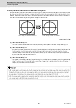
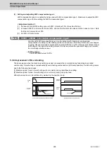
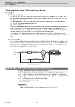
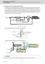
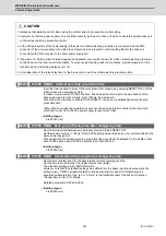
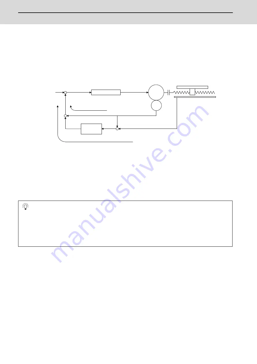
5.4.3 Dual Feedback Control
If the motor and machine coupling or machine system's rigidity is low (ex. large machine, etc.) when using a closed loop
system, the response during acceleration/deceleration will vibrate and cause overshooting. This can cause the position
loop gain from increasing. The dual feedback function is effective in this case.
To validate the dual feedback function, use position feedback with a motor side encoder in ranges with high acceleration
to enable stable control. In ranges with low acceleration, use position feedback with the machine side encoder (scale).
This will make it possible to increase the position loop gain.
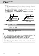
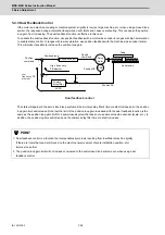
The state will approach the semi-closed loop system as the primary delay filter's time constant increases, so the position
loop gain limit will increase. Note that the limit of the position loop gain increased with the dual feedback function is the
same as the position loop gain limit for a semi-closed system that does not use a machine side encoder (scale, etc.). In
addition, the positioning time will increase as the primary delay filter time constant increases.
POINT
1. Dual feedback control is a function that compensates symptoms resulting from insufficient machine rigidity.
If there are items that can be improved on the machine (improvement of scale installation position, etc.)
improve those first.
2. The position loop gain limit will not increase compared to the semi-closed loop system even when using dual
feedback control.
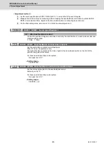
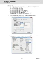
ENC
SV051
+
+
+
-
-
-
Position control
Primary
delay filter
High frequency
FB element
Position
command
Position droop
Servo
motor
Linear scale
Table
Speed
command
Position FB
Position FB
Dual feedback control
Low
frequency FB
element
Summary of Contents for MDS-E
Page 1: ......
Page 3: ......
Page 15: ......
Page 17: ......
Page 19: ......
Page 21: ......
Page 31: ......
Page 32: ...1 IB 1501229 F 1 Installation ...
Page 76: ...45 IB 1501229 F 2 Wiring and Connection ...
Page 132: ...101 IB 1501229 F 3 Safety Function ...
Page 142: ...111 IB 1501229 F 4 Setup ...
Page 277: ...MDS E EH Series Instruction Manual 4 Setup 246 IB 1501229 F ...
Page 278: ...247 IB 1501229 F 5 Servo Adjustment ...
Page 351: ...MDS E EH Series Instruction Manual 5 Servo Adjustment 320 IB 1501229 F ...
Page 352: ...321 IB 1501229 F 6 Spindle Adjustment ...
Page 404: ...373 IB 1501229 F 7 Troubleshooting ...
Page 455: ...MDS E EH Series Instruction Manual 7 Troubleshooting 424 IB 1501229 F ...
Page 456: ...425 IB 1501229 F 8 Maintenance ...
Page 475: ...MDS E EH Series Instruction Manual 8 Maintenance 444 IB 1501229 F ...
Page 476: ...445 IB 1501229 F 9 Power Backup System ...
Page 494: ...463 IB 1501229 F 10 Appx 1 Cable and Connector Assembly ...
Page 504: ...473 IB 1501229 F 11 Appx 2 D A Output Specifications for Drive Unit ...
Page 514: ...483 IB 1501229 F 12 Appx 3 Protection Function ...
Page 523: ...MDS E EH Series Instruction Manual 12 Appx 3 Protection Function 492 IB 1501229 F ...
Page 524: ...493 IB 1501229 F 13 Appx 4 Compliance to EC Directives ...
Page 528: ...497 IB 1501229 F 14 Appx 5 EMC Installation Guidelines ...
Page 540: ...509 IB 1501229 F 15 Appx 6 Higher Harmonic Suppression Measure Guidelines ...
Page 550: ......
Page 554: ......


