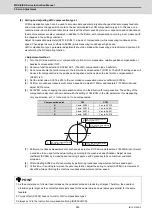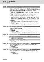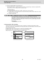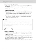
MDS-E/EH Series Instruction Manual
5 Servo Adjustment
297
IB-1501229-F
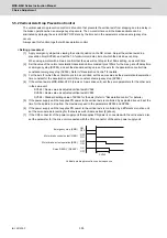
5.5 Settings for Emergency Stop
Emergency stop in this section refers to the following states.
[1] Emergency stop was input (including other axis alarms)
[2] NC power down was detected
[3] A drive unit alarm was detected
5.5.1 Deceleration Control
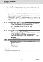
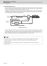
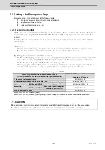
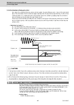
With the servo drive unit, if the deceleration stop function is validated, the motor will decelerate following the set time
constant while maintaining the READY ON state. READY will turn OFF and the dynamic brakes will function after
stopping.
If an alarm, for which dynamic brakes are designated as the stopping method, occurs, the motor will stop with the
dynamic brakes.
< Features >
When the load inertia is large, deceleration stop can be executed at a shorter time than the dynamic brakes.
(The stop time for the normal acceleration/deceleration time constants will be achieved.)
(1) Setting the deceleration control time constant
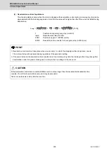
Set the time for stopping from the rapid traverse rate (rapid: axis specification parameter) in the deceleration time
constant for emergency stop (SV056: EMGt). The operation stops with the position loop step when 0 is set.
For the standard setting value of SV056, refer to the following table.
When applying this setting to the synchronous control axes, set the same value with negative symbol to the both
axes. Even if the dynamic break stop is applied to either axis, it is also applied to the other axis.
Standard setting value of SV056
#2004: G0tL G0 time constant (linear)
#2005: G0t1 G0 time constant (primary delay) / Second-step time constant for soft acceleration/deceleration
#2003: smgst Acceleration and deceleration modes
bit 3-0: Rapid traverse acceleration/deceleration type (hexadecimal)
SV056: EMGt Deceleration time constant
at emergency stop
Standard setting value
1:Linear acceleration/deceleration
EMGt
≤
G0tL× 0.9
8:Exponential acceleration and linear deceleration
EMGt
≤
(2×G0t1)× 0.9
F:Soft acceleration/
deceleration
#1219:aux03/bit7=0
Accelerating/decelerating time
is G0tL
EMGt
≤
(G0tL-G0t1)× 0.9
#1219:aux03/bit7=1
Accelerating/decelerating time
is obtained by G0tL+G0t1
EMGt
≤
G0tL× 0.9
A value other than the above
EMGt
≤
G0tL× 0.9
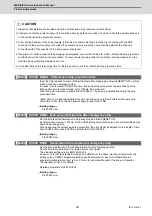
CAUTION
If the deceleration control time constant at emergency stop (EMGt) is set to a value longer than the above value,
the soft limit point (stroke end point) may be exceeded. Take care as the axis could collide the machine.
Summary of Contents for MDS-E
Page 1: ......
Page 3: ......
Page 15: ......
Page 17: ......
Page 19: ......
Page 21: ......
Page 31: ......
Page 32: ...1 IB 1501229 F 1 Installation ...
Page 76: ...45 IB 1501229 F 2 Wiring and Connection ...
Page 132: ...101 IB 1501229 F 3 Safety Function ...
Page 142: ...111 IB 1501229 F 4 Setup ...
Page 277: ...MDS E EH Series Instruction Manual 4 Setup 246 IB 1501229 F ...
Page 278: ...247 IB 1501229 F 5 Servo Adjustment ...
Page 351: ...MDS E EH Series Instruction Manual 5 Servo Adjustment 320 IB 1501229 F ...
Page 352: ...321 IB 1501229 F 6 Spindle Adjustment ...
Page 404: ...373 IB 1501229 F 7 Troubleshooting ...
Page 455: ...MDS E EH Series Instruction Manual 7 Troubleshooting 424 IB 1501229 F ...
Page 456: ...425 IB 1501229 F 8 Maintenance ...
Page 475: ...MDS E EH Series Instruction Manual 8 Maintenance 444 IB 1501229 F ...
Page 476: ...445 IB 1501229 F 9 Power Backup System ...
Page 494: ...463 IB 1501229 F 10 Appx 1 Cable and Connector Assembly ...
Page 504: ...473 IB 1501229 F 11 Appx 2 D A Output Specifications for Drive Unit ...
Page 514: ...483 IB 1501229 F 12 Appx 3 Protection Function ...
Page 523: ...MDS E EH Series Instruction Manual 12 Appx 3 Protection Function 492 IB 1501229 F ...
Page 524: ...493 IB 1501229 F 13 Appx 4 Compliance to EC Directives ...
Page 528: ...497 IB 1501229 F 14 Appx 5 EMC Installation Guidelines ...
Page 540: ...509 IB 1501229 F 15 Appx 6 Higher Harmonic Suppression Measure Guidelines ...
Page 550: ......
Page 554: ......

