
MDS-E/EH Series Instruction Manual
5 Servo Adjustment
301
IB-1501229-F
【
#2248
】
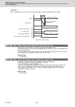
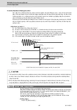
SV048 EMGrt Vertical axis drop prevention time
Input the time required to prevent the vertical axis from dropping by delaying READY OFF until the
brake works at an emergency stop.
Increase in increments of 100ms at a time, find and set the value where the axis does not drop.
When using a motor with a break, set to "200ms" as a standard.
When the pull up function is enabled (SV033/bitE=1), the pull up is established during the drop
prevention time.
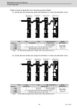
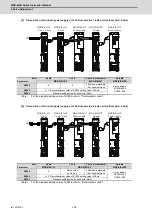
(Note) When not using the spindle drive unit, use the servo axis that controls vertical axis drop
prevention control to control the power supply (connect with CN4).
---Setting range---
0 to 20000 (ms)
【
#2255
】
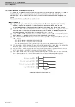
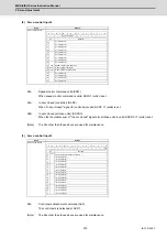
SV055 EMGx Max. gate off delay time after emergency stop
Set the time required between an emergency stop and forced READY OFF.
Set the maximum value "+ 100ms" of the SV056 setting value of the servo drive unit electrified by the
same power supply unit.
When executing the vertical axis drop prevention, the gate off will be delayed for the length of time
set at SV048 even when SV055's is smaller than that of SV048.
---Setting range---
0 to 20000 (ms)
【
#2256
】
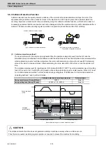
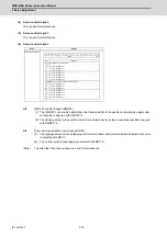
SV056 EMGt Deceleration time constant at emergency stop
Set the time constant used for the deceleration control at emergency stop.
Set the time required to stop from rapid traverse rate (rapid).
The standard setting value is EMGt
≤
G0tL×0.9.
However, note that the standard setting value differs from the above-mentioned value when the
setting value of "#2003:smgst Acceleration and deceleration modes bit 3-0:Rapid traverse
acceleration/deceleration type" is 8 or F. Refer to Instruction Manual of the drive unit (section
"Deceleration control") for details.
Related parameters: SV048, SV055
---Setting range---
0 to 20000 (ms)
CAUTION
1. Always set deceleration control when using the vertical axis drop prevention control setting.
2. Configure so that the power supply unit is controlled directly by the servo drive unit which controls the spindle drive unit
or the vertical axis drop prevention control.
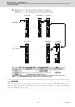
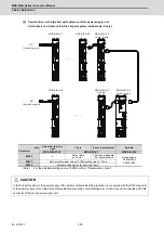
3. In the 2nd part system of the power supply, if the axis for vertical axis drop prevention is connected with the CN9
connector of the power supply unit, provide the vertical axis drop prevention control setting also for the drive unit
connected with CN4 connector of the same power supply unit.
4. If an alarm, for which dynamic brake stopping is designated, occurs with the axis for which vertical axis drop prevention
control is active, the function will not activate. To prevent axis dropping under all conditions, provide measures on the
machine side by installing a balance unit, etc.
5. In consideration of the relay delay time for the break control, set the vertical axis drop prevention time.
Summary of Contents for MDS-E
Page 1: ......
Page 3: ......
Page 15: ......
Page 17: ......
Page 19: ......
Page 21: ......
Page 31: ......
Page 32: ...1 IB 1501229 F 1 Installation ...
Page 76: ...45 IB 1501229 F 2 Wiring and Connection ...
Page 132: ...101 IB 1501229 F 3 Safety Function ...
Page 142: ...111 IB 1501229 F 4 Setup ...
Page 277: ...MDS E EH Series Instruction Manual 4 Setup 246 IB 1501229 F ...
Page 278: ...247 IB 1501229 F 5 Servo Adjustment ...
Page 351: ...MDS E EH Series Instruction Manual 5 Servo Adjustment 320 IB 1501229 F ...
Page 352: ...321 IB 1501229 F 6 Spindle Adjustment ...
Page 404: ...373 IB 1501229 F 7 Troubleshooting ...
Page 455: ...MDS E EH Series Instruction Manual 7 Troubleshooting 424 IB 1501229 F ...
Page 456: ...425 IB 1501229 F 8 Maintenance ...
Page 475: ...MDS E EH Series Instruction Manual 8 Maintenance 444 IB 1501229 F ...
Page 476: ...445 IB 1501229 F 9 Power Backup System ...
Page 494: ...463 IB 1501229 F 10 Appx 1 Cable and Connector Assembly ...
Page 504: ...473 IB 1501229 F 11 Appx 2 D A Output Specifications for Drive Unit ...
Page 514: ...483 IB 1501229 F 12 Appx 3 Protection Function ...
Page 523: ...MDS E EH Series Instruction Manual 12 Appx 3 Protection Function 492 IB 1501229 F ...
Page 524: ...493 IB 1501229 F 13 Appx 4 Compliance to EC Directives ...
Page 528: ...497 IB 1501229 F 14 Appx 5 EMC Installation Guidelines ...
Page 540: ...509 IB 1501229 F 15 Appx 6 Higher Harmonic Suppression Measure Guidelines ...
Page 550: ......
Page 554: ......


