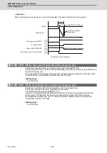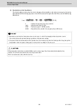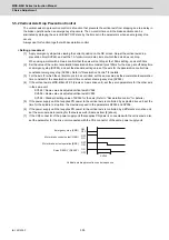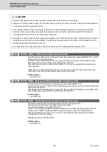
MDS-E/EH Series Instruction Manual
5 Servo Adjustment
308
IB-1501229-F
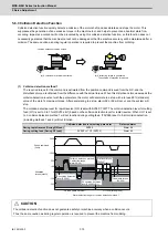
【
#2233
】
SV033 SSF2 Servo function 2
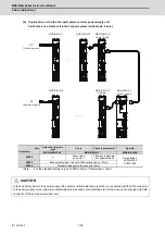
bit E : zup Vertical axis pull up function
0: Stop 1: Enable
【
#2248
】
SV048 EMGrt Vertical axis drop prevention time
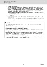
Input the time required to prevent the vertical axis from dropping by delaying READY OFF until the
brake works at an emergency stop.
Increase in increments of 100ms at a time, find and set the value where the axis does not drop.
When using a motor with a break, set to "200ms" as a standard.
When the pull up function is enabled (SV033/bitE=1), the pull up is established during the drop
prevention time.
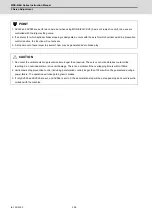
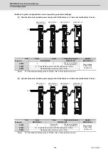
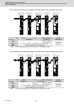
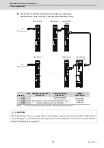
(Note) When not using the spindle drive unit, use the servo axis that controls vertical axis drop
prevention control to control the power supply (connect with CN4).
---Setting range---
0 to 20000 (ms)
【
#2295
】
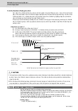
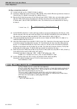
SV095 ZUPD Vertical axis pull up distance
Set this parameter to adjust the pull up distance when the vertical axis pull up function is enabled.
When the pull up function is enabled and this parameter is set to "0", for a rotary motor, 8/1000 of a
rotation at the motor end is internally set as the pull up distance, and for a linear motor, 80[
μ
m] is
set.
---Setting range---
0 to 2000 (
μ
m)
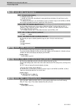
5.6 Protective Functions
5.6.1 Overload Detection
The servo drive unit is equipped with an electronic thermal that protects the servo motor and servo drive unit from
overload conditions. The overload 1 alarm (alarm 50) is detected if an overload condition occurs, and the overload 2
alarm (alarm 51) is detected if 95% or more of the maximum current is commanded continuously for 1 second or longer
due to a machine collision, etc. The parameters shown below are for Mitsubishi adjustment purposes only, and should be
kept at their standard settings (SV021=60, SV022=150).
【
#2221
】
SV021 OLT Overload detection time constant
Normally, set to "60". (For Mitsubishi adjustment.)
---Setting range---
1 to 999 (s)
【
#2222
】
SV022 OLL Overload detection level
Set the "Overload 1" (Alarm 50) current detection level as percentage to the stall current.
Normally set this parameter to "150". (For Mitsubishi adjustment.)
---Setting range---
110 to 500 (Stall current %)
For details concerning the overload protection characteristics, refer to the MDS-E/EH Series Specifications
Manual (IB-1501226).
Summary of Contents for MDS-E
Page 1: ......
Page 3: ......
Page 15: ......
Page 17: ......
Page 19: ......
Page 21: ......
Page 31: ......
Page 32: ...1 IB 1501229 F 1 Installation ...
Page 76: ...45 IB 1501229 F 2 Wiring and Connection ...
Page 132: ...101 IB 1501229 F 3 Safety Function ...
Page 142: ...111 IB 1501229 F 4 Setup ...
Page 277: ...MDS E EH Series Instruction Manual 4 Setup 246 IB 1501229 F ...
Page 278: ...247 IB 1501229 F 5 Servo Adjustment ...
Page 351: ...MDS E EH Series Instruction Manual 5 Servo Adjustment 320 IB 1501229 F ...
Page 352: ...321 IB 1501229 F 6 Spindle Adjustment ...
Page 404: ...373 IB 1501229 F 7 Troubleshooting ...
Page 455: ...MDS E EH Series Instruction Manual 7 Troubleshooting 424 IB 1501229 F ...
Page 456: ...425 IB 1501229 F 8 Maintenance ...
Page 475: ...MDS E EH Series Instruction Manual 8 Maintenance 444 IB 1501229 F ...
Page 476: ...445 IB 1501229 F 9 Power Backup System ...
Page 494: ...463 IB 1501229 F 10 Appx 1 Cable and Connector Assembly ...
Page 504: ...473 IB 1501229 F 11 Appx 2 D A Output Specifications for Drive Unit ...
Page 514: ...483 IB 1501229 F 12 Appx 3 Protection Function ...
Page 523: ...MDS E EH Series Instruction Manual 12 Appx 3 Protection Function 492 IB 1501229 F ...
Page 524: ...493 IB 1501229 F 13 Appx 4 Compliance to EC Directives ...
Page 528: ...497 IB 1501229 F 14 Appx 5 EMC Installation Guidelines ...
Page 540: ...509 IB 1501229 F 15 Appx 6 Higher Harmonic Suppression Measure Guidelines ...
Page 550: ......
Page 554: ......

