


MDS-E/EH Series Instruction Manual
5 Servo Adjustment
309
IB-1501229-F
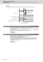
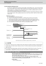
5.6.2 Excessive Error Detection
An excessive error (alarms 52, 53, 54) is detected when the difference between the servo's commanded position and the
FB position exceeds the value set by parameter. Separate excessive error detection width can be set for servo ON
(SV023) and servo OFF (SV026) statuses. When a wider excessive error detection width than that used for standard
control is required in stopper control, etc., the detection width setting can be changed to the SV053 setting value by NC
command.
Follow-up control (NC commanded position tracks servo FB position) is used during emergency stop and during a servo
OFF command, and so there is no excessive error detection at those times, although the follow-up control during a servo
OFF status can be disabled by an NC system parameter setting.
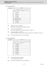
【
#2223
】
SV023 OD1 Excessive error detection width during servo ON
Set the excessive error detection width in servo ON.
<Standard setting value>
OD1=OD2= (Rapid traverse rate [mm/min]) / (60×PGN1) / 2 [mm]
When set to "0", the excessive error alarm detection will be ignored, so do not set to "0".
---Setting range---
0 to 32767 (mm)
However, when SV084/bitC=1, the setting range is from 0 to 32767 (
μ
m).
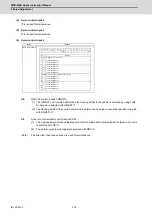
【
#2226
】
SV026 OD2 Excessive error detection width during servo OFF
Set the excessive error detection width during servo OFF.
<Standard setting value>
OD1=OD2= (Rapid traverse rate [mm/min]) / (60×PGN1) / 2 [mm]
When set to "0", the excessive error alarm detention will be ignored, so do not set to "0".
---Setting range---
0 to 32767 (mm)
However, when SV084/bitC=1, the setting range is from 0 to 32767 (
μ
m).
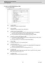
【
#2253
】
SV053 OD3 Excessive error detection width in special control
Set the excessive error detection width when servo ON in a special control (initial absolute position
setting, stopper control and etc.).
When "0" is set, excessive error detection will not be performed when servo ON during a special
control.
---Setting range---
0 to 32767 (mm)
However, when SV084/bitC=1, the setting range is from 0 to 32767 (
μ
m).
Summary of Contents for MDS-E
Page 1: ......
Page 3: ......
Page 15: ......
Page 17: ......
Page 19: ......
Page 21: ......
Page 31: ......
Page 32: ...1 IB 1501229 F 1 Installation ...
Page 76: ...45 IB 1501229 F 2 Wiring and Connection ...
Page 132: ...101 IB 1501229 F 3 Safety Function ...
Page 142: ...111 IB 1501229 F 4 Setup ...
Page 277: ...MDS E EH Series Instruction Manual 4 Setup 246 IB 1501229 F ...
Page 278: ...247 IB 1501229 F 5 Servo Adjustment ...
Page 351: ...MDS E EH Series Instruction Manual 5 Servo Adjustment 320 IB 1501229 F ...
Page 352: ...321 IB 1501229 F 6 Spindle Adjustment ...
Page 404: ...373 IB 1501229 F 7 Troubleshooting ...
Page 455: ...MDS E EH Series Instruction Manual 7 Troubleshooting 424 IB 1501229 F ...
Page 456: ...425 IB 1501229 F 8 Maintenance ...
Page 475: ...MDS E EH Series Instruction Manual 8 Maintenance 444 IB 1501229 F ...
Page 476: ...445 IB 1501229 F 9 Power Backup System ...
Page 494: ...463 IB 1501229 F 10 Appx 1 Cable and Connector Assembly ...
Page 504: ...473 IB 1501229 F 11 Appx 2 D A Output Specifications for Drive Unit ...
Page 514: ...483 IB 1501229 F 12 Appx 3 Protection Function ...
Page 523: ...MDS E EH Series Instruction Manual 12 Appx 3 Protection Function 492 IB 1501229 F ...
Page 524: ...493 IB 1501229 F 13 Appx 4 Compliance to EC Directives ...
Page 528: ...497 IB 1501229 F 14 Appx 5 EMC Installation Guidelines ...
Page 540: ...509 IB 1501229 F 15 Appx 6 Higher Harmonic Suppression Measure Guidelines ...
Page 550: ......
Page 554: ......


