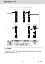
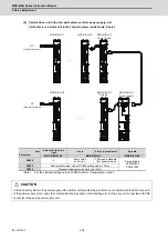


MDS-E/EH Series Instruction Manual
5 Servo Adjustment
311
IB-1501229-F
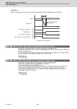
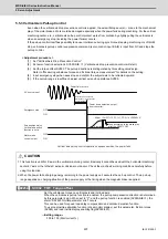
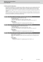
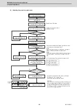
(2) Collision detection method 2
When the current command reaches the motor's maximum current, the motor will decelerate and stop at a torque
80% (standard value) of the motor's maximum torque. After decelerating to a stop, alarm 5A will occur, and the
system will stop. If the acceleration/deceleration time constant is short and incorrect detections easily occur during
normal operation, lengthen the acceleration/ deceleration time constant and adjust so that the current is not
saturated (does not reach the maximum current) during acceleration.
If the acceleration/deceleration time constant cannot be lengthened, set parameter SV035/bitB (SSF4.c12n) to 1 to
ignore collision detection method 2.
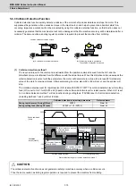
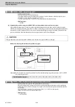
(3) Retracting torque
In each collision detection method, impact after a collision is reduced by generating the retracting torque after the
collision is detected.
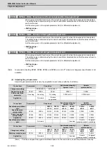
The retracting torque is a torque 70% to 100% which is set with SV035: SSF4/cltq (bit8, bit9) based on the current
of the motor maximum ability.
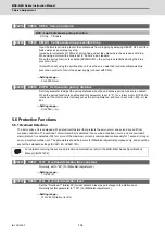
POINT
1. Validate SHG control or OMR-FF function when using the collision detection function, or when carrying out SV059
setting value operation.
2. Provide an allowance in the detection level setting to prevent incorrect detections.
3. All collision detection functions will be disabled when SV60 is set to 0.
4. Collision detection method 2 will function if a value other than 0 is set in SV060. Note that the detection can be ignored
by setting the parameter (SV035/bitB).
5. The torque estimated gain (SV059) must be readjusted when there are changes in the encoder replacement following
maintenance, etc., in the encoder resolution, or in the position control system such as encoder loop gain (PGN), etc.
(closed loop control and semi-closed loop has been changed).
6. The retracting torque generated when a collision is detected outputs the motor maximum torque. If the torque limitation is
required in order to protect the machine, set "SV035 : SSF4/cltq (bit8, bit9)".
Summary of Contents for MDS-E
Page 1: ......
Page 3: ......
Page 15: ......
Page 17: ......
Page 19: ......
Page 21: ......
Page 31: ......
Page 32: ...1 IB 1501229 F 1 Installation ...
Page 76: ...45 IB 1501229 F 2 Wiring and Connection ...
Page 132: ...101 IB 1501229 F 3 Safety Function ...
Page 142: ...111 IB 1501229 F 4 Setup ...
Page 277: ...MDS E EH Series Instruction Manual 4 Setup 246 IB 1501229 F ...
Page 278: ...247 IB 1501229 F 5 Servo Adjustment ...
Page 351: ...MDS E EH Series Instruction Manual 5 Servo Adjustment 320 IB 1501229 F ...
Page 352: ...321 IB 1501229 F 6 Spindle Adjustment ...
Page 404: ...373 IB 1501229 F 7 Troubleshooting ...
Page 455: ...MDS E EH Series Instruction Manual 7 Troubleshooting 424 IB 1501229 F ...
Page 456: ...425 IB 1501229 F 8 Maintenance ...
Page 475: ...MDS E EH Series Instruction Manual 8 Maintenance 444 IB 1501229 F ...
Page 476: ...445 IB 1501229 F 9 Power Backup System ...
Page 494: ...463 IB 1501229 F 10 Appx 1 Cable and Connector Assembly ...
Page 504: ...473 IB 1501229 F 11 Appx 2 D A Output Specifications for Drive Unit ...
Page 514: ...483 IB 1501229 F 12 Appx 3 Protection Function ...
Page 523: ...MDS E EH Series Instruction Manual 12 Appx 3 Protection Function 492 IB 1501229 F ...
Page 524: ...493 IB 1501229 F 13 Appx 4 Compliance to EC Directives ...
Page 528: ...497 IB 1501229 F 14 Appx 5 EMC Installation Guidelines ...
Page 540: ...509 IB 1501229 F 15 Appx 6 Higher Harmonic Suppression Measure Guidelines ...
Page 550: ......
Page 554: ......


