


MDS-E/EH Series Instruction Manual
5 Servo Adjustment
312
IB-1501229-F
< Setting and adjustment methods >
[1] Confirm that SHG control or OMR-FF function is enabled.
[2] Set the axis unbalanced torque to the torque offset (SV032: TOF). (Refer to "Measuring unbalance torque and
frictional torque" for details on measuring the unbalance torque.)
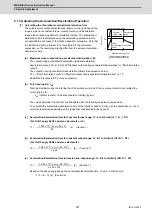
[3] Measure the frictional torque and set in the frictional torque (SV045: TRUB). Carry out reciprocation operation
(approx. F1000) with the axis to be adjusted, and measure the load current % when the axis is fed at the
constant speed on the NC SERVO MONITOR screen. This frictional torque is expressed with the following
expression.
[4] Set SV035: SSF4.clt (bitF) to 1 for the axis being adjusted, and move in both directions with JOG, etc., at the
rapid traverse rate. When the load inertia ratio display on the NC SERVO MONITOR screen has stabilized, set
that value for the torque estimated gain (SV059: TCNV). Return SV035: SSF4.clt (bitF) to 0.
[5] If the acceleration/deceleration time is short, and the current is limited, set SV035: SSF4.c12n (bitB) to 1 to
invalidate collision detection method 2.
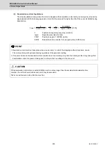
[6] Adjust the collision detection level (SV060: TLMT). First set 100. If operation at the rapid traverse rate results
in an alarm, increase the setting value by approx. 20. If an alarm does not occur, lower the setting value by
approx. 10. The estimated disturbance torque value on the servo monitor screen will indicate the estimated
disturbance torque peak value for the latest two seconds. This value can be used as reference. Set the final
setting value to a value approx. 1.5-fold the limit value at which an alarm does not occur.
[7] Divide the maximum cutting load with the value set for the collision detection level (SV060: TLMT). (Round up
the decimal) Set this value in SV035: SSF4.clG1 (bitC-E).
(Example) For maximum cutting load: 200%, SV060: TLMT setting value: 80%
200/80=2.5 -> The detection level is 3 (-fold), so set SV035:SSF4 to "3xxx".
[8] Set the retracting torque when the a collision is detected to SV035: SSF4.cltq (bit8,9).
(Example) To set the retracting torque to 70% of the motor maximum torque:
Set SV035:SSF4 to "x3xx".
【
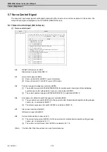
#2232
】
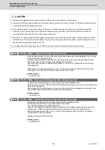
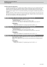
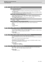
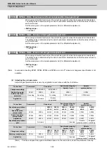
SV032 TOF Torque offset
Set the unbalance torque on vertical axis and inclined axis.
When the vertical axis pull up function is enabled, the pull up compensation direction is determined
by this parameter's sign. When set to "0", and the pull up function is enabled (SV033/bitE=1),the
alarm "S02 2233 Initial parameter error" occurs.
This can be used for speed loop delay compensation and collision detection function.
To use load inertia estimation function (drive monitor display), set this parameter, friction torque
(SV045) and load inertia display enabling flag(SV035/bitF).
---Setting range---
-100 to 100 (Stall current %)
2
=
(+ feed load current %) - (- feed load current %)
Frictional torque (%)
Summary of Contents for MDS-E
Page 1: ......
Page 3: ......
Page 15: ......
Page 17: ......
Page 19: ......
Page 21: ......
Page 31: ......
Page 32: ...1 IB 1501229 F 1 Installation ...
Page 76: ...45 IB 1501229 F 2 Wiring and Connection ...
Page 132: ...101 IB 1501229 F 3 Safety Function ...
Page 142: ...111 IB 1501229 F 4 Setup ...
Page 277: ...MDS E EH Series Instruction Manual 4 Setup 246 IB 1501229 F ...
Page 278: ...247 IB 1501229 F 5 Servo Adjustment ...
Page 351: ...MDS E EH Series Instruction Manual 5 Servo Adjustment 320 IB 1501229 F ...
Page 352: ...321 IB 1501229 F 6 Spindle Adjustment ...
Page 404: ...373 IB 1501229 F 7 Troubleshooting ...
Page 455: ...MDS E EH Series Instruction Manual 7 Troubleshooting 424 IB 1501229 F ...
Page 456: ...425 IB 1501229 F 8 Maintenance ...
Page 475: ...MDS E EH Series Instruction Manual 8 Maintenance 444 IB 1501229 F ...
Page 476: ...445 IB 1501229 F 9 Power Backup System ...
Page 494: ...463 IB 1501229 F 10 Appx 1 Cable and Connector Assembly ...
Page 504: ...473 IB 1501229 F 11 Appx 2 D A Output Specifications for Drive Unit ...
Page 514: ...483 IB 1501229 F 12 Appx 3 Protection Function ...
Page 523: ...MDS E EH Series Instruction Manual 12 Appx 3 Protection Function 492 IB 1501229 F ...
Page 524: ...493 IB 1501229 F 13 Appx 4 Compliance to EC Directives ...
Page 528: ...497 IB 1501229 F 14 Appx 5 EMC Installation Guidelines ...
Page 540: ...509 IB 1501229 F 15 Appx 6 Higher Harmonic Suppression Measure Guidelines ...
Page 550: ......
Page 554: ......


