


MDS-E/EH Series Instruction Manual
5 Servo Adjustment
313
IB-1501229-F
【
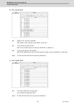
#2235
】
SV035 SSF4 Servo function 4
bit F : clt Inertia ratio display
0: Setting for normal use
1: Display the total inertia ratio estimated at acceleration/deceleration at the inertia ratio on the
servo monitor screen
To display it on the screen, set an imbalance torque and friction torque to both SV032 and SV045
and repeat acceleration/deceleration operations for several times.
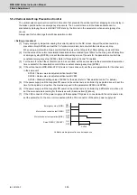
bit E-C: clG1 G1 Collision detection level
Set the collision detection level in the collision detection method 1 during cutting feed (G1) in
multiples of that of rapid traverse (G0). When set to "0", detection of collision detection method 1
during cutting feed will be ignored.
G1 Collision detection level = G0 collision detection level (SV060) × clG1
bit B : cl2n Collision detection method 2
0: Enable 1: Disable
bit 9-8 : cltq Retract torque in collision detection
Set the retract torque in collision detection using the ratio of motor's maximum torque.
bit9,8=
00: 100%
01: 90%
10: 80% (Standard)
11: 70%
【
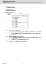
#2245
】
SV045 TRUB Friction torque
Set the frictional torque when using the collision detection function.
To use load inertia estimation function (drive monitor display), set this parameter, imbalance torque
(SV032) and load inertia display enabling flag (SV035/bitF).
---Setting range---
0 to 255 (Stall current %)
【
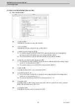
#2259
】
SV059 TCNV Collision detection torque estimated gain
Set the torque estimated gain when using the collision detection function.
The standard setting value is the same as the load inertia ratio (SV037 setting value) including motor
inertia.
Set to "0" when not using the collision detection function.
<<Drive monitor load inertia ratio display>>
Set SV035/bitF=1 and imbalance torque and friction torque to both SV032 and SV045, and then
repeat acceleration/deceleration for several times.
---Setting range---
For general motor: 0 to 5000 (%)
For linear motor: 0 to 5000 (kg)
【
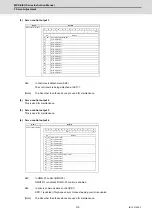
#2260
】
SV060 TLMT Collision detection level
When using the collision detection function, set the collision detection level at the G0 feeding.
When "0" is set, none of the collision detection function will work.
---Setting range---
0 to 999 (Stall current %)
Summary of Contents for MDS-E
Page 1: ......
Page 3: ......
Page 15: ......
Page 17: ......
Page 19: ......
Page 21: ......
Page 31: ......
Page 32: ...1 IB 1501229 F 1 Installation ...
Page 76: ...45 IB 1501229 F 2 Wiring and Connection ...
Page 132: ...101 IB 1501229 F 3 Safety Function ...
Page 142: ...111 IB 1501229 F 4 Setup ...
Page 277: ...MDS E EH Series Instruction Manual 4 Setup 246 IB 1501229 F ...
Page 278: ...247 IB 1501229 F 5 Servo Adjustment ...
Page 351: ...MDS E EH Series Instruction Manual 5 Servo Adjustment 320 IB 1501229 F ...
Page 352: ...321 IB 1501229 F 6 Spindle Adjustment ...
Page 404: ...373 IB 1501229 F 7 Troubleshooting ...
Page 455: ...MDS E EH Series Instruction Manual 7 Troubleshooting 424 IB 1501229 F ...
Page 456: ...425 IB 1501229 F 8 Maintenance ...
Page 475: ...MDS E EH Series Instruction Manual 8 Maintenance 444 IB 1501229 F ...
Page 476: ...445 IB 1501229 F 9 Power Backup System ...
Page 494: ...463 IB 1501229 F 10 Appx 1 Cable and Connector Assembly ...
Page 504: ...473 IB 1501229 F 11 Appx 2 D A Output Specifications for Drive Unit ...
Page 514: ...483 IB 1501229 F 12 Appx 3 Protection Function ...
Page 523: ...MDS E EH Series Instruction Manual 12 Appx 3 Protection Function 492 IB 1501229 F ...
Page 524: ...493 IB 1501229 F 13 Appx 4 Compliance to EC Directives ...
Page 528: ...497 IB 1501229 F 14 Appx 5 EMC Installation Guidelines ...
Page 540: ...509 IB 1501229 F 15 Appx 6 Higher Harmonic Suppression Measure Guidelines ...
Page 550: ......
Page 554: ......


