MDS-E/EH Series Instruction Manual
6 Spindle Adjustment
322
IB-1501229-F
6.1 Adjustment Procedures for Each Control
6.1.1 Basic Adjustments
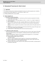
(1) Items to check during trial operation
[1] When the power is ON for the first time, check the wiring. When the machine is operated for the first time,
check the set parameters again.
[2] Confirm that the values of the NC side parameters "slimt1 to 4", "smax1 to 4", and "smini" comply with the
machine specification.
[3] When the machine running-in has not been completed, gradually raise the rotation speed (in increments of
1000r/min) for the spindle. Raise the speed at the timing when the load meter value is stabilized during
rotation.
If the load meter value is higher than the normal value, stop the operation and check the spindle section of the
machine.
[4] Confirm that the command (S command) speed and actual speed match during running-in. When gear ratio is
set, the spindle end speed and motor speed differ.
[5] Confirm that there is no abnormal noise, odor or motor overheat during running-in.
(2) Adjusting the spindle rotation speed
When the spindle motor and the spindle end are coupled using a gear or pulley, the rotation speeds of the spindle
motor and the spindle end may not match. Adjust the command and the rotation speed of spindle end with the
following method.
Apply the following adjustment methods [1] to [3] individually to each of the gears 00 to 11. Confirm that the
machine's gear changes correctly before the adjustment.
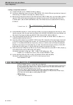
[1] Set the spindle specification parameters, "slimt1 to 4".
Calculation expression:
slimt1 to 4 = SP026 × (deceleration rate of the gears 00 to 11 between the motor and spindle end)
[2] Set the S command to half of the maximum spindle rotation speed and confirm the rotation speed of the
spindle end. Adjust slimt1 to 4 until the rotation speed matches.
[3] Set the S command to the maximum spindle end rotation speed and confirm that the S command speed and
the spindle end speed match.
CAUTION
1. Do not adjust when possible risks associated with adjustment procedures are not thoroughly taken into consideration.
2. Be careful when touching rotating section, or your hand may be caught in or cut.
3. Changing of parameters has to be done carefully.
Summary of Contents for MDS-E
Page 1: ......
Page 3: ......
Page 15: ......
Page 17: ......
Page 19: ......
Page 21: ......
Page 31: ......
Page 32: ...1 IB 1501229 F 1 Installation ...
Page 76: ...45 IB 1501229 F 2 Wiring and Connection ...
Page 132: ...101 IB 1501229 F 3 Safety Function ...
Page 142: ...111 IB 1501229 F 4 Setup ...
Page 277: ...MDS E EH Series Instruction Manual 4 Setup 246 IB 1501229 F ...
Page 278: ...247 IB 1501229 F 5 Servo Adjustment ...
Page 351: ...MDS E EH Series Instruction Manual 5 Servo Adjustment 320 IB 1501229 F ...
Page 352: ...321 IB 1501229 F 6 Spindle Adjustment ...
Page 404: ...373 IB 1501229 F 7 Troubleshooting ...
Page 455: ...MDS E EH Series Instruction Manual 7 Troubleshooting 424 IB 1501229 F ...
Page 456: ...425 IB 1501229 F 8 Maintenance ...
Page 475: ...MDS E EH Series Instruction Manual 8 Maintenance 444 IB 1501229 F ...
Page 476: ...445 IB 1501229 F 9 Power Backup System ...
Page 494: ...463 IB 1501229 F 10 Appx 1 Cable and Connector Assembly ...
Page 504: ...473 IB 1501229 F 11 Appx 2 D A Output Specifications for Drive Unit ...
Page 514: ...483 IB 1501229 F 12 Appx 3 Protection Function ...
Page 523: ...MDS E EH Series Instruction Manual 12 Appx 3 Protection Function 492 IB 1501229 F ...
Page 524: ...493 IB 1501229 F 13 Appx 4 Compliance to EC Directives ...
Page 528: ...497 IB 1501229 F 14 Appx 5 EMC Installation Guidelines ...
Page 540: ...509 IB 1501229 F 15 Appx 6 Higher Harmonic Suppression Measure Guidelines ...
Page 550: ......
Page 554: ......

