


MDS-E/EH Series Instruction Manual
6 Spindle Adjustment
324
IB-1501229-F
【
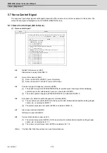
#13082
】
SP082 IDAL D axis current lead compensation low-speed coil
When using coil switch function, set the current loop gain for when the low-speed coil is selected.
The setting value is determined by the motor's electrical characteristics so that the value is fixed to
each motor used.
Set the value given in the spindle parameter list. (For Mitsubishi adjustment)
---Setting range---
1 to 20480
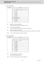
【
#13083
】
SP083 IQGL Q axis current gain low-speed coil
When using coil switch function, set the current loop gain for when the low-speed coil is selected.
The setting value is determined by the motor's electrical characteristics so that the value is fixed to
each motor used.
Set the value given in the spindle parameter list. (For Mitsubishi adjustment)
---Setting range---
1 to 8192
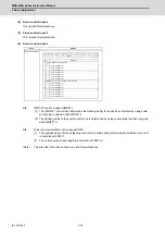
【
#13084
】
SP084 IDGL D axis current gain low-speed coil
When using coil switch function, set the current loop gain for when the low-speed coil is selected.
The setting value is determined by the motor's electrical characteristics so that the value is fixed to
each motor used.
Set the value given in the spindle parameter list. (For Mitsubishi adjustment)
---Setting range---
1 to 8192
(Note)
Low-speed coil setting SP081, SP082, SP083 and SP084 are set to "0" when coil changeover specification is not
available.
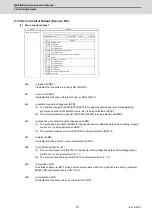
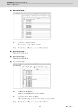
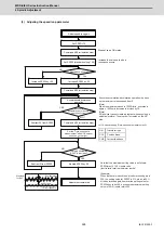
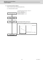
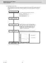
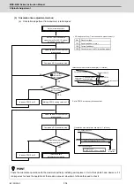
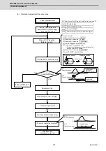
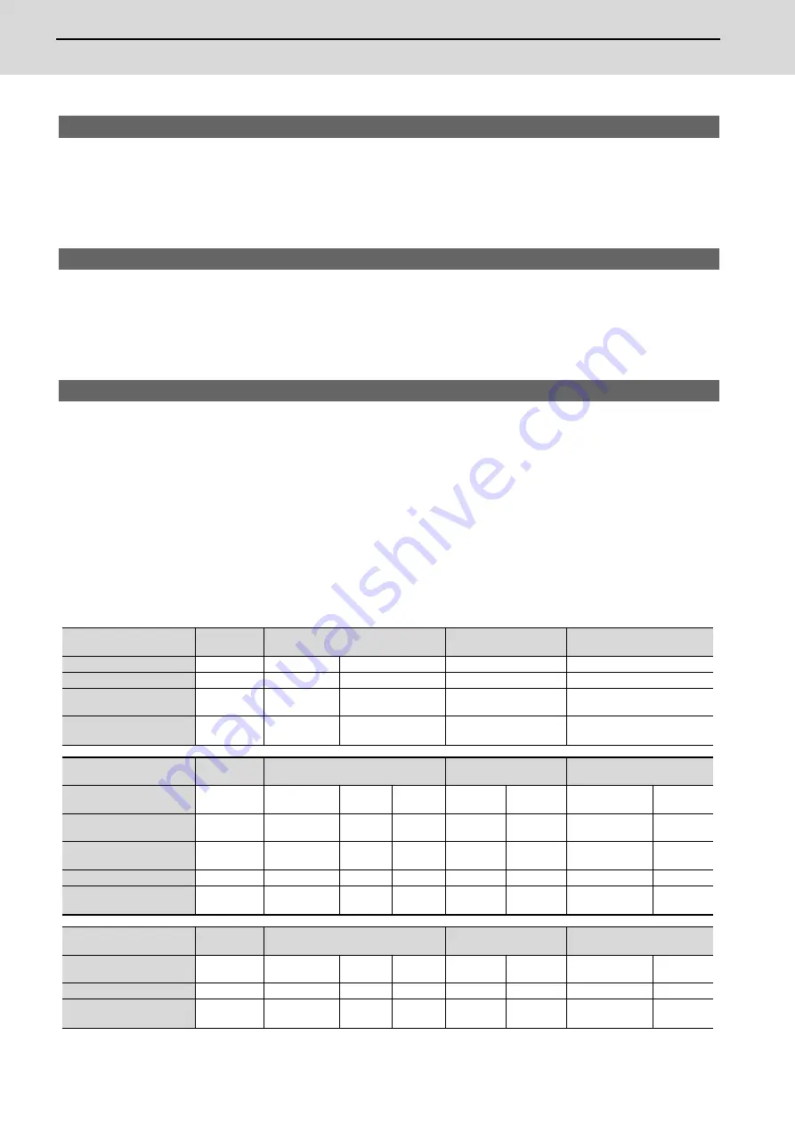
(2) Adjusting the gain parameter
Adjust the gain parameters as usual or by application in accordance with the chart below.
(Note)
Position and speed loop gain is switched depend on the control item, so set the parameter correctly.
Control item
S command
Orientation
Synchronous tapping/
Spindle C axis
Spindle
synchronization
Changeover setting
-
#3106/bitE=0
#3106/bitE=1
-
-
Position loop gain
SP001
SP002
SP001
SP002
SP003
SHG control start
parameter
No setting
No setting
No setting
SP035/bitC=1
SP036/bit4=1
Application
Standard
Vibration
suppression
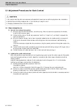
Control item
S command
Orientation
Synchronous tapping/
Spindle C axis
Spindle
synchronization
Speed loop proportional
gain
-
-
SP035/
bit1=0
SP035/
bit1=1
SP035/
bit9=0
SP035/
bit9=1
SP036/
bit1=0
SP036/
bit1=1
Speed loop lead
compensation
SP005
SP008
SP005
SP008
SP005
SP008
SP005
SP008
Speed loop delay
compensation
SP006
SP009
SP006
SP009
SP006
SP009
SP006
SP009
Application
SP007
SP010
SP007
SP010
SP007
SP010
SP007
SP010
Speed loop proportional
gain
Standard
Standard
Double
grasping control
Polygonal
machining
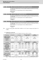
Control item
S command
Orientation
Synchronous tapping/
Spindle C axis
Spindle
synchronization
Changeover setting
-
-
SP035/
bit2=0
SP035/
bit2=1
SP035/
bitA=0
SP035/
bitA=1
SP036/
bit2=0
SP036/
bit2=1
Minimum excitation rate
SP014
SP015
SP014
SP015
SP014
SP015
SP014
SP015
Application
Standard
Standard
Double
grasping control
Polygonal
machining
Summary of Contents for MDS-E
Page 1: ......
Page 3: ......
Page 15: ......
Page 17: ......
Page 19: ......
Page 21: ......
Page 31: ......
Page 32: ...1 IB 1501229 F 1 Installation ...
Page 76: ...45 IB 1501229 F 2 Wiring and Connection ...
Page 132: ...101 IB 1501229 F 3 Safety Function ...
Page 142: ...111 IB 1501229 F 4 Setup ...
Page 277: ...MDS E EH Series Instruction Manual 4 Setup 246 IB 1501229 F ...
Page 278: ...247 IB 1501229 F 5 Servo Adjustment ...
Page 351: ...MDS E EH Series Instruction Manual 5 Servo Adjustment 320 IB 1501229 F ...
Page 352: ...321 IB 1501229 F 6 Spindle Adjustment ...
Page 404: ...373 IB 1501229 F 7 Troubleshooting ...
Page 455: ...MDS E EH Series Instruction Manual 7 Troubleshooting 424 IB 1501229 F ...
Page 456: ...425 IB 1501229 F 8 Maintenance ...
Page 475: ...MDS E EH Series Instruction Manual 8 Maintenance 444 IB 1501229 F ...
Page 476: ...445 IB 1501229 F 9 Power Backup System ...
Page 494: ...463 IB 1501229 F 10 Appx 1 Cable and Connector Assembly ...
Page 504: ...473 IB 1501229 F 11 Appx 2 D A Output Specifications for Drive Unit ...
Page 514: ...483 IB 1501229 F 12 Appx 3 Protection Function ...
Page 523: ...MDS E EH Series Instruction Manual 12 Appx 3 Protection Function 492 IB 1501229 F ...
Page 524: ...493 IB 1501229 F 13 Appx 4 Compliance to EC Directives ...
Page 528: ...497 IB 1501229 F 14 Appx 5 EMC Installation Guidelines ...
Page 540: ...509 IB 1501229 F 15 Appx 6 Higher Harmonic Suppression Measure Guidelines ...
Page 550: ......
Page 554: ......


