MDS-E/EH Series Instruction Manual
6 Spindle Adjustment
325
IB-1501229-F
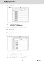
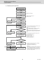
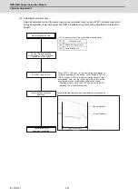
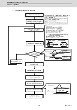
(3) Adjusting the speed loop parameter
CH1
CH2
Yes
NO
YES
NO
0
0
NO
YES
Stops at servo ON status
Increase the value up to where
resonance occurs.
Set SP005 (standard setting 150)
Command M19 (orientation stop)
Adjust speed loop gain
Set SP001=15
Resonance occurs?
Increase SP005 by +20
Command M19 (orientation stop)
Increase SP005 by -20
Subtract 20 from SP005
Acceleration/deceleration
operation
Resonance
(abnormal noise) or abnormal
operation occurs?
Command M19 (orientation stop)
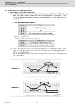
Waveform
for Ref.
0.045
°
or less
Position droop
Adjustment completed
Multiply SP005 by 0.9
Subtract 3 from SP005
Is droop oscillation
0.045°p-p or less?
Note that the maximum setting value is as follows:
SP005(max) ≤ 150 × inertia ratio
(Inertia ratio
:
total inertia/motor inertia
)
(Example)
When inertia rate is double and the determined gain is
350, the setting value for SP005 is 315, which is 90%
of the determined gain, however,the setting value for
SP005 should be 300, because the maximum setting
value is 150×2(inertia rate)=300.
Executes acceleration/deceleration operation in phase
up to maximum rotation speed from 0.
(Note)
When the maximum speed is 10000r/min, executes in
approx. 1000r/min increments, divided by 10.
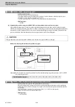
(Note)
NC analyzer cannot create a program when acquiring a
spindle waveform. The program is created on the NC
side.
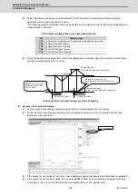
< NC Analyzer setting (Time-series data measurement) >
Set the "Time-series data
measurement" with NC Analyzer
as shown on the right.
Get
Waveform type
Position droop
Current feedback
Current feedback
Summary of Contents for MDS-E
Page 1: ......
Page 3: ......
Page 15: ......
Page 17: ......
Page 19: ......
Page 21: ......
Page 31: ......
Page 32: ...1 IB 1501229 F 1 Installation ...
Page 76: ...45 IB 1501229 F 2 Wiring and Connection ...
Page 132: ...101 IB 1501229 F 3 Safety Function ...
Page 142: ...111 IB 1501229 F 4 Setup ...
Page 277: ...MDS E EH Series Instruction Manual 4 Setup 246 IB 1501229 F ...
Page 278: ...247 IB 1501229 F 5 Servo Adjustment ...
Page 351: ...MDS E EH Series Instruction Manual 5 Servo Adjustment 320 IB 1501229 F ...
Page 352: ...321 IB 1501229 F 6 Spindle Adjustment ...
Page 404: ...373 IB 1501229 F 7 Troubleshooting ...
Page 455: ...MDS E EH Series Instruction Manual 7 Troubleshooting 424 IB 1501229 F ...
Page 456: ...425 IB 1501229 F 8 Maintenance ...
Page 475: ...MDS E EH Series Instruction Manual 8 Maintenance 444 IB 1501229 F ...
Page 476: ...445 IB 1501229 F 9 Power Backup System ...
Page 494: ...463 IB 1501229 F 10 Appx 1 Cable and Connector Assembly ...
Page 504: ...473 IB 1501229 F 11 Appx 2 D A Output Specifications for Drive Unit ...
Page 514: ...483 IB 1501229 F 12 Appx 3 Protection Function ...
Page 523: ...MDS E EH Series Instruction Manual 12 Appx 3 Protection Function 492 IB 1501229 F ...
Page 524: ...493 IB 1501229 F 13 Appx 4 Compliance to EC Directives ...
Page 528: ...497 IB 1501229 F 14 Appx 5 EMC Installation Guidelines ...
Page 540: ...509 IB 1501229 F 15 Appx 6 Higher Harmonic Suppression Measure Guidelines ...
Page 550: ......
Page 554: ......

