


MDS-E/EH Series Instruction Manual
6 Spindle Adjustment
328
IB-1501229-F
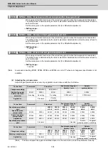
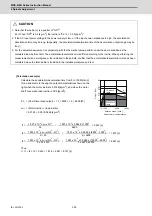
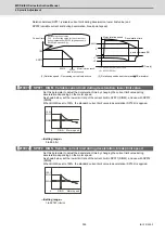
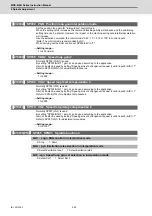
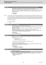
[Calculation example]
Calculate the acceleration/deceleration time from 0 to 10000[r/min]
for an spindle motor having the output characteristics shown on the
right when the motor inertia is 0.0148 [kg•m
2
], and when the motor
shaft conversion load inertia is 0.05 [kg•m
2
].
Po = (Short-time rated output) × 1.2 = 5500 × 1.2 = 6600 [W]
J
all
= (Motor inertia) + (load inertia)
= 0.0148 + 0.05 =0.0648 [kg•m
2
]
Thus,
t = t1 + t2 + t3 = 0.242 + 1.818 + 4.691 = 6.751 [s]
CAUTION
1. Note that the inertia (J) is a quarter of "GD
2
".
Ex.) When "GD
2
" is 0.2 [kg•m
2
], the inertia is "0.2 / 4 = 0.05 [kg•m
2
]".
2. If the AC input power voltage to the power supply is low, or if the input power impedance is high, the acceleration/
deceleration time may be long. (Especially, the acceleration/deceleration time of the deceleration output range may be
long.)
3. For the actual measurement in comparison with the theoretical value, perform under the same condition as the
calculated load inertia of Jall. The acceleration/deceleration time differs according to the inertia. When performing the
measurement with a workpiece or tool installed to the spindle, confirm that the acceleration/deceleration time has been
calculated when the total inertia is included in the installed workpiece and tool.
0 1500
6000
0
2.0
6.0
8.0
4.0
Out
p
ut
[
kW
]
10000
15-minute
rating
3.7
5.5
4.1
Continuous
rating
Rotation speed [ r/min ]
Spindle motor characteristics
2.8
1.097 x 10
-2
x J
all
x N1
2
1.097
x
10
-2
x 0.0648 x 1500
2
t1 =
Po
=
6600
= 0.242 [s]
1.097 x 10
-2
x J
all
x (N2
2
- N1
2
) 1.097
x
10
-2
x 0.0648 x (6000
2
- 1500
2
)
t2 =
2
Po
=
2
6600
= 1.818 [s]
1.097 x 10
-2
x J
all
x (N3
3
- N2
3
) 1.097
x
10
-2
x 0.0648 x (10000
3
- 6000
3
)
t3 =
3 x Po x N2
=
3 x 6600 x 6000
= 4.691 [s]
Summary of Contents for MDS-E
Page 1: ......
Page 3: ......
Page 15: ......
Page 17: ......
Page 19: ......
Page 21: ......
Page 31: ......
Page 32: ...1 IB 1501229 F 1 Installation ...
Page 76: ...45 IB 1501229 F 2 Wiring and Connection ...
Page 132: ...101 IB 1501229 F 3 Safety Function ...
Page 142: ...111 IB 1501229 F 4 Setup ...
Page 277: ...MDS E EH Series Instruction Manual 4 Setup 246 IB 1501229 F ...
Page 278: ...247 IB 1501229 F 5 Servo Adjustment ...
Page 351: ...MDS E EH Series Instruction Manual 5 Servo Adjustment 320 IB 1501229 F ...
Page 352: ...321 IB 1501229 F 6 Spindle Adjustment ...
Page 404: ...373 IB 1501229 F 7 Troubleshooting ...
Page 455: ...MDS E EH Series Instruction Manual 7 Troubleshooting 424 IB 1501229 F ...
Page 456: ...425 IB 1501229 F 8 Maintenance ...
Page 475: ...MDS E EH Series Instruction Manual 8 Maintenance 444 IB 1501229 F ...
Page 476: ...445 IB 1501229 F 9 Power Backup System ...
Page 494: ...463 IB 1501229 F 10 Appx 1 Cable and Connector Assembly ...
Page 504: ...473 IB 1501229 F 11 Appx 2 D A Output Specifications for Drive Unit ...
Page 514: ...483 IB 1501229 F 12 Appx 3 Protection Function ...
Page 523: ...MDS E EH Series Instruction Manual 12 Appx 3 Protection Function 492 IB 1501229 F ...
Page 524: ...493 IB 1501229 F 13 Appx 4 Compliance to EC Directives ...
Page 528: ...497 IB 1501229 F 14 Appx 5 EMC Installation Guidelines ...
Page 540: ...509 IB 1501229 F 15 Appx 6 Higher Harmonic Suppression Measure Guidelines ...
Page 550: ......
Page 554: ......


