


MDS-E/EH Series Instruction Manual
1 Installation
5
IB-1501229-F
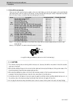
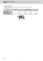
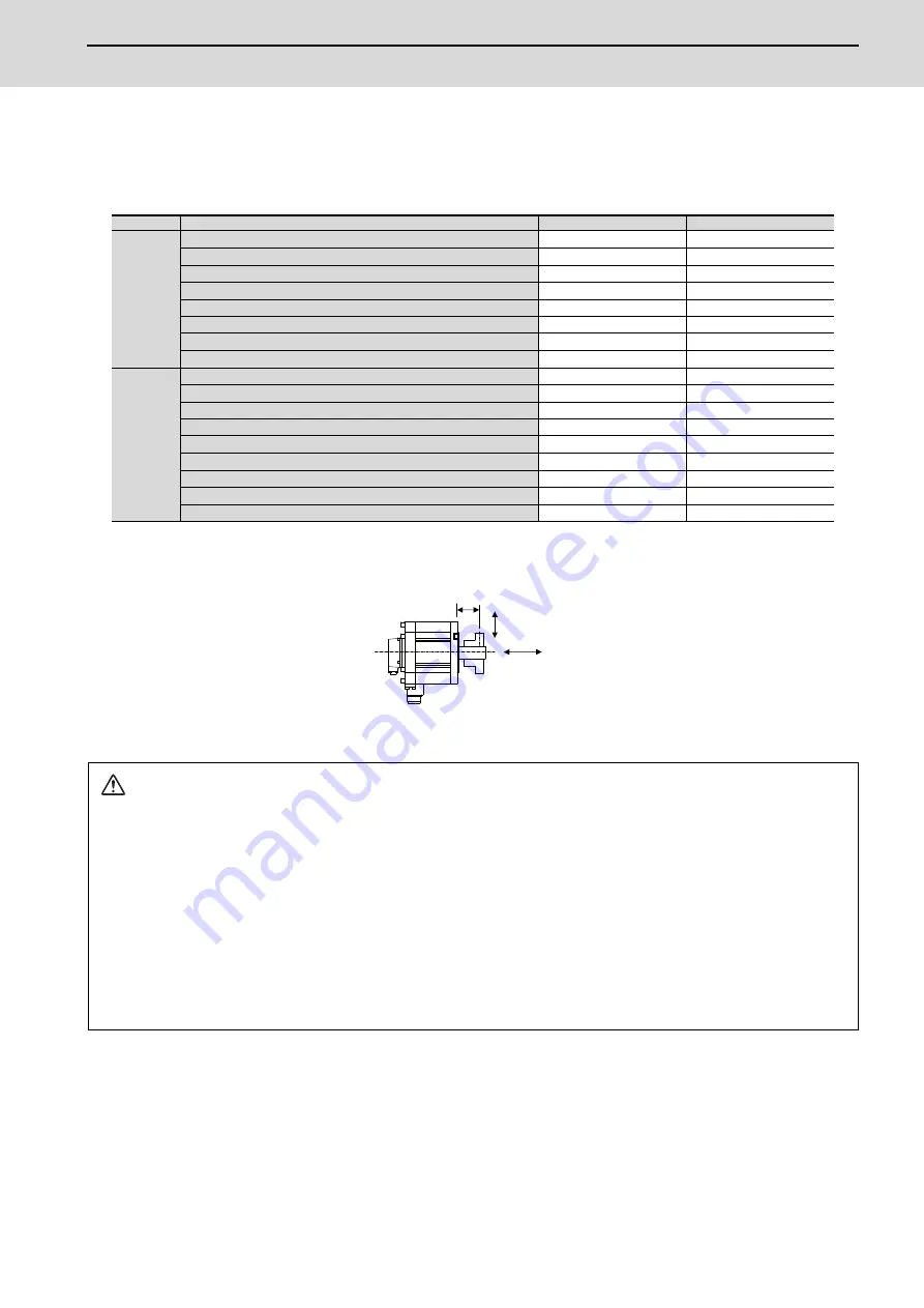
1.1.5 Shaft Characteristics
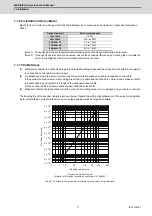
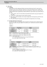
There is a limit to the load that can be applied on the motor shaft. Make sure that the load applied on the radial direction
and thrust direction, when mounted on the machine, is below the tolerable values given below. These loads may affect
the motor output torque, so consider them when designing the machine.
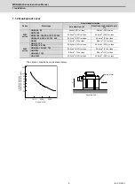
(Note 1) The tolerable radial load and thrust load in the above table are values applied when each motor is used
independently.
(Note 2) The symbol L in the table refers to the value of L below.
L: Length from flange installation surface to center of load mass [mm]
Series
Servo motor
Tolerable radial load
Tolerable thrust load
200V
series
HG46S, HG56S (Straight shaft)
245N (L=30)
98N
HG96S (Straight shaft)
392N (L=40)
147N
HG75T, 105T (Taper shaft)
245N (L=33)
147N
HG75S, 105S (Straight shaft)
245N (L=33)
147N
HG54T, 104T, 154T, 224T, 123T, 223T, 142T (Taper shaft)
392N (L=58)
490N
HG54S, 104S, 154S, 224S, 123S, 223S, 142S (Straight shaft)
980N (L=55)
490N
HG204S, 354S, 303S, 453S, 703S, 302S (Straight shaft)
2058N (L=79)
980N
HG903S (Straight shaft)
2450N (L=85)
980N
400V
series
HG-H75T, 105T (Taper shaft)
245N (L=33)
147N
HG-H75S, 105S (Straight shaft)
245N (L=33)
147N
HG-H54T, 104T, 154T (Taper shaft)
392N (L=58)
490N
HG-H54S, 104S, 154S (Straight shaft)
980N (L=55)
490N
HG-H204S, 354S, 453S, 703S (Straight shaft)
2058N (L=79)
980N
HG-H903S (Straight shaft)
2450N (L=85)
980N
HG-H1502S (Straight shaft)
3234N (L=140)
1470N
HQ-H903S (Straight shaft)
2500N (L=52.7)
1100N
HQ-H1103S (Straight shaft)
2700N (L=52.7)
1500N
CAUTION
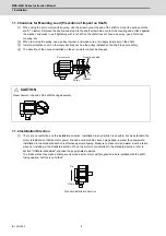
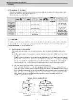
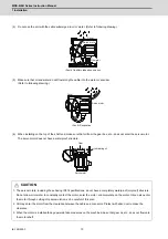
1. Use a flexible coupling when connecting with a ball screw, etc., and keep the shaft core deviation to below the tolerable
radial load of the shaft.
2. When directly installing the gear on the motor shaft, the radial load increases as the diameter of the gear decreases. This
should be carefully considered when designing the machine.
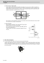
3. When directly installing the pulley on the motor shaft, carefully consider so that the radial load (double the tension)
generated from the timing belt tension is less than the values shown in the table above.
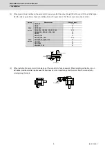
4. In machines where thrust loads such as a worm gear are applied, carefully consider providing separate bearings, etc., on
the machine side so that loads exceeding the tolerable thrust loads are not applied to the motor.
5. Do not apply the loads exceeding the tolerable level. Failure to observe this may lead to the axis or bearing damage.
Radial load
Thrust load
L
Summary of Contents for MDS-E
Page 1: ......
Page 3: ......
Page 15: ......
Page 17: ......
Page 19: ......
Page 21: ......
Page 31: ......
Page 32: ...1 IB 1501229 F 1 Installation ...
Page 76: ...45 IB 1501229 F 2 Wiring and Connection ...
Page 132: ...101 IB 1501229 F 3 Safety Function ...
Page 142: ...111 IB 1501229 F 4 Setup ...
Page 277: ...MDS E EH Series Instruction Manual 4 Setup 246 IB 1501229 F ...
Page 278: ...247 IB 1501229 F 5 Servo Adjustment ...
Page 351: ...MDS E EH Series Instruction Manual 5 Servo Adjustment 320 IB 1501229 F ...
Page 352: ...321 IB 1501229 F 6 Spindle Adjustment ...
Page 404: ...373 IB 1501229 F 7 Troubleshooting ...
Page 455: ...MDS E EH Series Instruction Manual 7 Troubleshooting 424 IB 1501229 F ...
Page 456: ...425 IB 1501229 F 8 Maintenance ...
Page 475: ...MDS E EH Series Instruction Manual 8 Maintenance 444 IB 1501229 F ...
Page 476: ...445 IB 1501229 F 9 Power Backup System ...
Page 494: ...463 IB 1501229 F 10 Appx 1 Cable and Connector Assembly ...
Page 504: ...473 IB 1501229 F 11 Appx 2 D A Output Specifications for Drive Unit ...
Page 514: ...483 IB 1501229 F 12 Appx 3 Protection Function ...
Page 523: ...MDS E EH Series Instruction Manual 12 Appx 3 Protection Function 492 IB 1501229 F ...
Page 524: ...493 IB 1501229 F 13 Appx 4 Compliance to EC Directives ...
Page 528: ...497 IB 1501229 F 14 Appx 5 EMC Installation Guidelines ...
Page 540: ...509 IB 1501229 F 15 Appx 6 Higher Harmonic Suppression Measure Guidelines ...
Page 550: ......
Page 554: ......


