


MDS-E/EH Series Instruction Manual
6 Spindle Adjustment
334
IB-1501229-F
6.1.4 Orientation Adjustment
Adjusts orientation time by adjusting SP016.
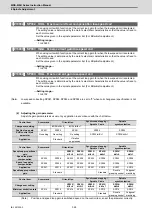
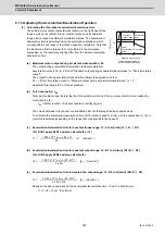
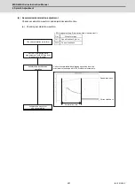
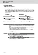
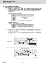
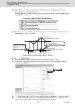
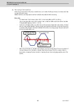
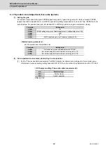
(1) Orientation characteristics
When decelerating to stop is executed with orientation, the remaining distance to the orientation stop position is
compensated within one rotation. Thus, as shown in Case 1 below, when the remaining distance in deceleration is
about "0", orientation time would be the shortest (time required to decelerate and stop + 0s), and as shown in Case
2 below, when the remaining distance in deceleration is about as much as one rotation amount, orientation time
would be the longest.
【
#13016
】
SP016 DDT Phase alignment deceleration rate
Set the single-rotation position alignment deceleration rate for orientation stopping, phase alignment
while rotating and switching from non-interpolation mode to spindle synchronization mode while
rotating.
When the load inertia is larger, the setting value should be smaller.
When the setting value is larger, the orientation in-position and single-rotation position alignment
complete faster, but the impact applied on the machine will increase.
To change the deceleration rate only during rotation command (command F
Δ
T
≠
0), set this
parameter together with SP070 (KDDT).
---Setting range---
1 to 32767 (0.1(r/min)/ms)
【
#13035(PR)
】
SP035 SFNC3 Spindle function 3
bit 2 : pyin Excitation rate selection in non-interpolation mode
The excitation rate after the in-position can be selected.
0: Select Excitation rate 1 1: Select Excitation rate 2
bit 1 : vgin Speed loop gain set selection in non-interpolation mode
The speed loop gain set after the in-position can be selected.
0: Select Set 1 1: Select Set 2
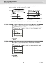
0
0
Time(s)
0
0
Time(s)
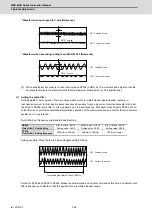
Case1: Remaining distance at deceleration 0 rotation
Case2: Remaining distance at deceleration 1 rotation
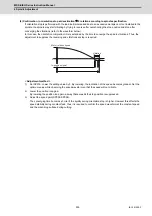
q axis current command (SP126: 1 SP128: 100)
Motor rotation speed
Current edge [1]
Current limit range at deceleration
(SP152 or SP184)
Motor rotation speed
Current edge [2]
q axis current command
q axis current command
Summary of Contents for MDS-E
Page 1: ......
Page 3: ......
Page 15: ......
Page 17: ......
Page 19: ......
Page 21: ......
Page 31: ......
Page 32: ...1 IB 1501229 F 1 Installation ...
Page 76: ...45 IB 1501229 F 2 Wiring and Connection ...
Page 132: ...101 IB 1501229 F 3 Safety Function ...
Page 142: ...111 IB 1501229 F 4 Setup ...
Page 277: ...MDS E EH Series Instruction Manual 4 Setup 246 IB 1501229 F ...
Page 278: ...247 IB 1501229 F 5 Servo Adjustment ...
Page 351: ...MDS E EH Series Instruction Manual 5 Servo Adjustment 320 IB 1501229 F ...
Page 352: ...321 IB 1501229 F 6 Spindle Adjustment ...
Page 404: ...373 IB 1501229 F 7 Troubleshooting ...
Page 455: ...MDS E EH Series Instruction Manual 7 Troubleshooting 424 IB 1501229 F ...
Page 456: ...425 IB 1501229 F 8 Maintenance ...
Page 475: ...MDS E EH Series Instruction Manual 8 Maintenance 444 IB 1501229 F ...
Page 476: ...445 IB 1501229 F 9 Power Backup System ...
Page 494: ...463 IB 1501229 F 10 Appx 1 Cable and Connector Assembly ...
Page 504: ...473 IB 1501229 F 11 Appx 2 D A Output Specifications for Drive Unit ...
Page 514: ...483 IB 1501229 F 12 Appx 3 Protection Function ...
Page 523: ...MDS E EH Series Instruction Manual 12 Appx 3 Protection Function 492 IB 1501229 F ...
Page 524: ...493 IB 1501229 F 13 Appx 4 Compliance to EC Directives ...
Page 528: ...497 IB 1501229 F 14 Appx 5 EMC Installation Guidelines ...
Page 540: ...509 IB 1501229 F 15 Appx 6 Higher Harmonic Suppression Measure Guidelines ...
Page 550: ......
Page 554: ......


