
MDS-E/EH Series Instruction Manual
6 Spindle Adjustment
338
IB-1501229-F
6.1.5 Synchronous Tapping Adjustment
(1) Gain setting and time constant determination
[1] For speed loop gain during synchronous tapping, speed loop gain set 2, which consists of SP008 (speed loop
gain 2), SP009 (speed loop lead compensation 2), and SP010 (speed loop delay compensation 2), is used.
Thus, SP035 has to be set as follows. For position loop gain, set standard 33 to SP002 (position loop gain
interpolation mode).
< List of parameters used for adjustment >
< Related servo parameters >
Set the spindle and interpolation axis by tapping.
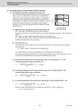
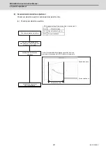
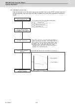
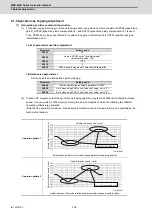
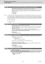
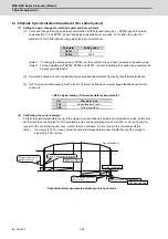
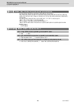
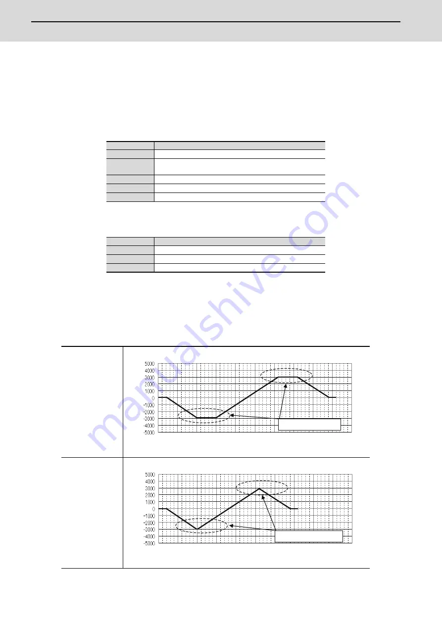
[2] Create a NC program so that the synchronous tapping operation program has 3000r/min of spindle rotation
speed, 1mm (equivalent of M6 screw) of screw pitch size, and depths at which the following two different
operation patterns are generated.
(Note that the operation conditions, such as spindle rotation speed and screw pitch, may be specified by the
machine tool builder.)
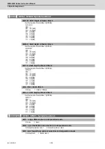
Parameter
Setting value
SP002
33
SP008
Value in SP005 set at "Gain Adjustment"
(Initial setting value: 150)
SP009
1900
SP010
0
SP035
0200: Speed loop gain set 2 selection (Validate bit9)
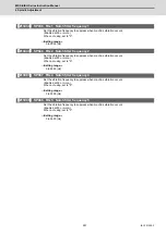
Parameter
Setting value
SV049
Set the same value as spindle parameter "SP002"
SV050
Set it when using SHG control (when not using, set to "0")
SV058
Set it when using SHG control (when not using, set to "0")
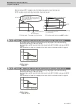
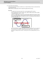
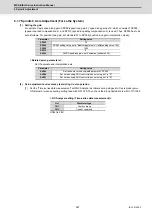
Operation pattern 1
Adjust depth so that motor rotation speed waveform shapes trapezoids
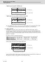
Operation pattern 2
Adjust depth so that motor rotation speed waveform shapes mountain-valley
Constant speed area
Spindle rotation speed (r/min)
S
p
indle rot
a
tion speed (r/
min)
Time (sec)
No constant speed area
Spindle rotation speed (r/min)
S
pindle rot
ation speed (r/
min)
Time (sec)
Summary of Contents for MDS-E
Page 1: ......
Page 3: ......
Page 15: ......
Page 17: ......
Page 19: ......
Page 21: ......
Page 31: ......
Page 32: ...1 IB 1501229 F 1 Installation ...
Page 76: ...45 IB 1501229 F 2 Wiring and Connection ...
Page 132: ...101 IB 1501229 F 3 Safety Function ...
Page 142: ...111 IB 1501229 F 4 Setup ...
Page 277: ...MDS E EH Series Instruction Manual 4 Setup 246 IB 1501229 F ...
Page 278: ...247 IB 1501229 F 5 Servo Adjustment ...
Page 351: ...MDS E EH Series Instruction Manual 5 Servo Adjustment 320 IB 1501229 F ...
Page 352: ...321 IB 1501229 F 6 Spindle Adjustment ...
Page 404: ...373 IB 1501229 F 7 Troubleshooting ...
Page 455: ...MDS E EH Series Instruction Manual 7 Troubleshooting 424 IB 1501229 F ...
Page 456: ...425 IB 1501229 F 8 Maintenance ...
Page 475: ...MDS E EH Series Instruction Manual 8 Maintenance 444 IB 1501229 F ...
Page 476: ...445 IB 1501229 F 9 Power Backup System ...
Page 494: ...463 IB 1501229 F 10 Appx 1 Cable and Connector Assembly ...
Page 504: ...473 IB 1501229 F 11 Appx 2 D A Output Specifications for Drive Unit ...
Page 514: ...483 IB 1501229 F 12 Appx 3 Protection Function ...
Page 523: ...MDS E EH Series Instruction Manual 12 Appx 3 Protection Function 492 IB 1501229 F ...
Page 524: ...493 IB 1501229 F 13 Appx 4 Compliance to EC Directives ...
Page 528: ...497 IB 1501229 F 14 Appx 5 EMC Installation Guidelines ...
Page 540: ...509 IB 1501229 F 15 Appx 6 Higher Harmonic Suppression Measure Guidelines ...
Page 550: ......
Page 554: ......


