
MDS-E/EH Series Instruction Manual
6 Spindle Adjustment
339
IB-1501229-F
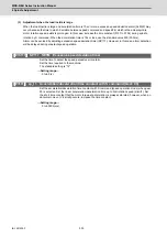
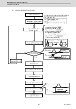
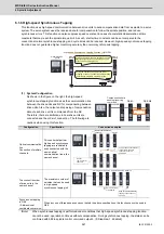
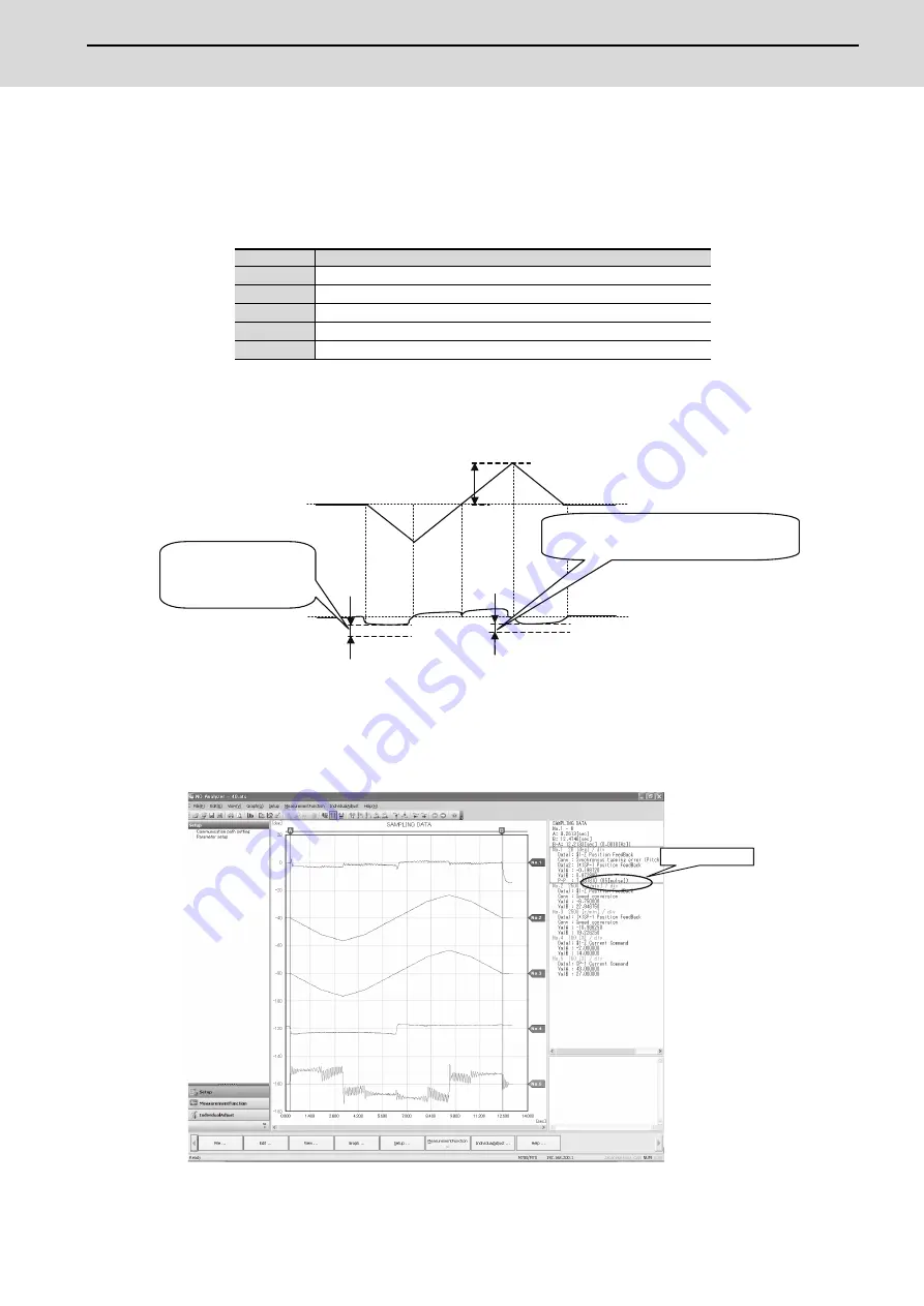
[3] Select "Synchronous tapping error measurement" on NC Analyzer, and perform synchronous tapping
operations with the operation pattern 2 above.
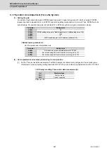
*The following measurement data of servo and spindle are automatically set when "Synchronous tapping error
measurement" is selected.
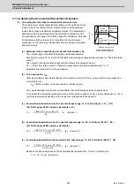
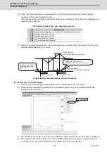
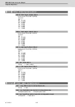
< NC Analyzer setting (Time-series data measurement) >
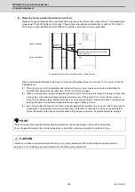
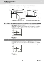
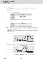
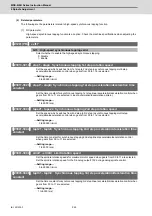
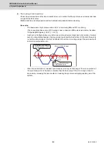
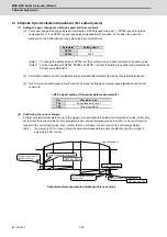
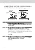
[4] Check the waveform and adjust the synchronous tapping time constant so that the margin for current limit at
acceleration/deceleration is 50% or more.
Output waveform example during synchronized tapping
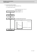
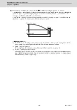
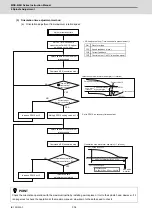
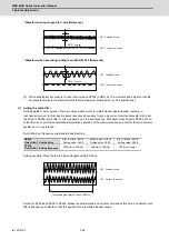
(2) Accuracy test using NC Analyzer
[1] Perform synchronous tapping operations using the time constant determined in (1) above.
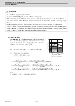
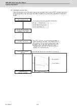
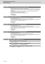
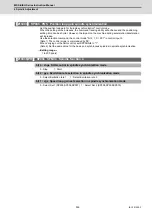
[2] Check the synchronous tapping accuracy (for both operation pattern 1 and 2) by using the synchronous
tapping accuracy check tool.
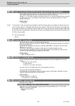
[3] If the number of error pulse is 100 (p-p) or less, satisfactory accuracy is secured, and the check is completed.
[4] If the number of error pulse exceeds 100, increase SP008 (VGN2) by 10 increments, and adjust so that the
error pulse is 100 or less. Note that the maximum setting value is 150 × [inertia ratio].
Get
Waveform type
CH1
Synchronous tapping error *Position error of spindle and servo axis
CH2
Speed feed back of servo
CH3
Speed feed back of spindle
CH4
Current feed back of servo
CH5
Current feed back of spindle
0
0
3000r/min
Current limit level
Current limit level
Margin for current limit at
acceleration has to be
50% or more.
Margin for current limit at
deceleration has to be 50% or more.
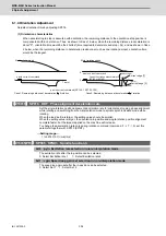
Speed feed back
(CH3: Speed feed back of spindle)
Current feed back
(CH5: Current feed back of spindle)
Error pulse display
Summary of Contents for MDS-E
Page 1: ......
Page 3: ......
Page 15: ......
Page 17: ......
Page 19: ......
Page 21: ......
Page 31: ......
Page 32: ...1 IB 1501229 F 1 Installation ...
Page 76: ...45 IB 1501229 F 2 Wiring and Connection ...
Page 132: ...101 IB 1501229 F 3 Safety Function ...
Page 142: ...111 IB 1501229 F 4 Setup ...
Page 277: ...MDS E EH Series Instruction Manual 4 Setup 246 IB 1501229 F ...
Page 278: ...247 IB 1501229 F 5 Servo Adjustment ...
Page 351: ...MDS E EH Series Instruction Manual 5 Servo Adjustment 320 IB 1501229 F ...
Page 352: ...321 IB 1501229 F 6 Spindle Adjustment ...
Page 404: ...373 IB 1501229 F 7 Troubleshooting ...
Page 455: ...MDS E EH Series Instruction Manual 7 Troubleshooting 424 IB 1501229 F ...
Page 456: ...425 IB 1501229 F 8 Maintenance ...
Page 475: ...MDS E EH Series Instruction Manual 8 Maintenance 444 IB 1501229 F ...
Page 476: ...445 IB 1501229 F 9 Power Backup System ...
Page 494: ...463 IB 1501229 F 10 Appx 1 Cable and Connector Assembly ...
Page 504: ...473 IB 1501229 F 11 Appx 2 D A Output Specifications for Drive Unit ...
Page 514: ...483 IB 1501229 F 12 Appx 3 Protection Function ...
Page 523: ...MDS E EH Series Instruction Manual 12 Appx 3 Protection Function 492 IB 1501229 F ...
Page 524: ...493 IB 1501229 F 13 Appx 4 Compliance to EC Directives ...
Page 528: ...497 IB 1501229 F 14 Appx 5 EMC Installation Guidelines ...
Page 540: ...509 IB 1501229 F 15 Appx 6 Higher Harmonic Suppression Measure Guidelines ...
Page 550: ......
Page 554: ......


