
MDS-E/EH Series Instruction Manual
6 Spindle Adjustment
348
IB-1501229-F
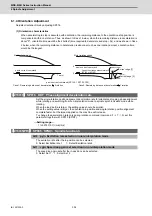
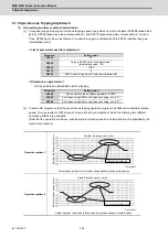
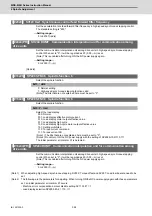
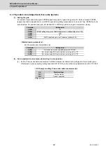
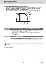
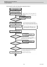
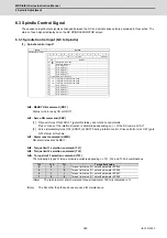
* Waveform during stopped in C axis (Reference)
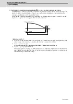
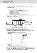
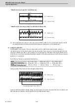
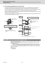
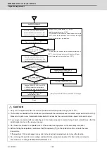
* Waveform when executing cutting feed with G01 F20 (Reference)
[2] When satisfactory accuracy is not secured, increase SP008 (VGN2) by 10 increments and adjust so that the
accuracy level meets the standard. Note that the maximum setting value is 150 x [inertia ratio].
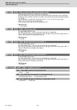
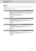
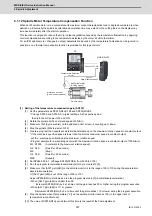
(3) Setting the notch filter
During spindle C axis operation, there are times where motor is rotated while brake is applied, resulting in
resonance occurred. In this case, measure resonance frequency from q axis current command waveform and set
the value to SP038 (notch filter 1). Also, depending on the set frequency, filter depth must be set to SP034. When
notch filter is set, perform acceleration/deceleration operation at the maximum speed and confirm that no abnormal
oscillation or noise is found.
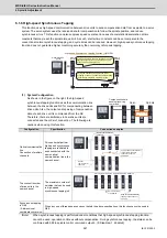
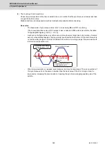
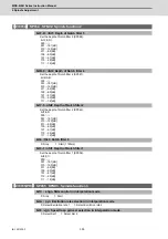
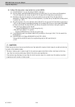
Notch filter's set frequency and standard depth setting
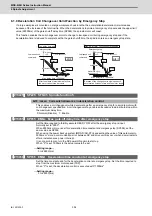
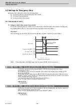
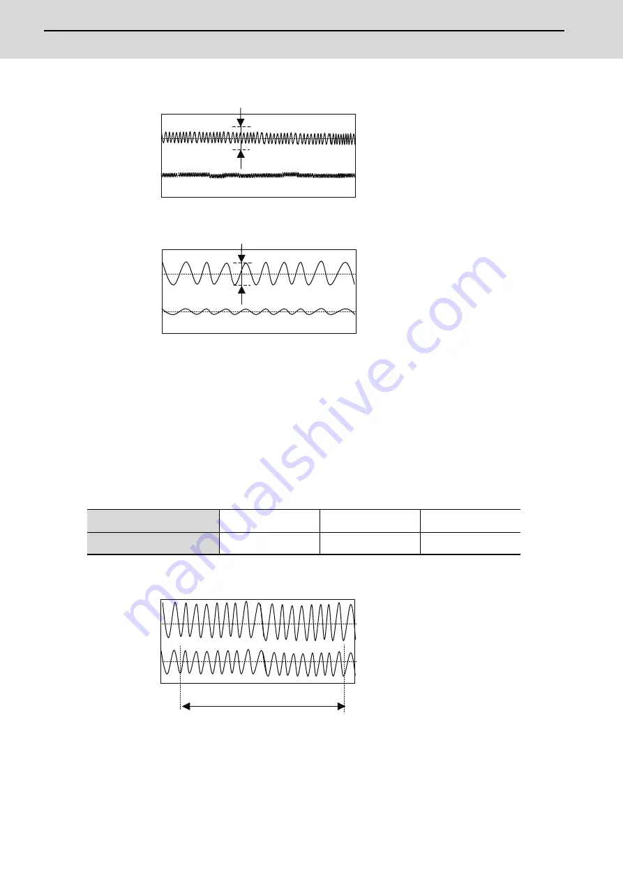
Setting example: When there are 16 wavelengths within 0.02 sec.
Set 800 to SP038 and XXX0 to SP034. Measure position droop and current command at this time, and adjust notch
filter's frequency and depth so that the position droop is within standard range.
SP034
Notch filter 1 Depth setting
bit3=0 bit2=0 bit1=0
Setting value: XXX0
bit3=0 bit2=1 bit1=0
Setting value: XXX4
bit3=1 bit2=0 bit1=0
Setting value: XXX8
SP038
Notch filter 1 Setting frequency
2000(Hz) to 400(Hz)
399(Hz) to 200(Hz)
190(Hz) or lower
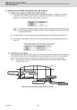
Ch1: Position droop
0
0
0.010° or less
Ch2: Current command
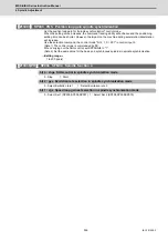
Ch1: Position droop
0
0
0.010° or less
Ch2: Current command
Ch1: Position droop
0
0
16 wavelengths within 0.02sec = 800Hz
Ch2: Current command
Summary of Contents for MDS-E
Page 1: ......
Page 3: ......
Page 15: ......
Page 17: ......
Page 19: ......
Page 21: ......
Page 31: ......
Page 32: ...1 IB 1501229 F 1 Installation ...
Page 76: ...45 IB 1501229 F 2 Wiring and Connection ...
Page 132: ...101 IB 1501229 F 3 Safety Function ...
Page 142: ...111 IB 1501229 F 4 Setup ...
Page 277: ...MDS E EH Series Instruction Manual 4 Setup 246 IB 1501229 F ...
Page 278: ...247 IB 1501229 F 5 Servo Adjustment ...
Page 351: ...MDS E EH Series Instruction Manual 5 Servo Adjustment 320 IB 1501229 F ...
Page 352: ...321 IB 1501229 F 6 Spindle Adjustment ...
Page 404: ...373 IB 1501229 F 7 Troubleshooting ...
Page 455: ...MDS E EH Series Instruction Manual 7 Troubleshooting 424 IB 1501229 F ...
Page 456: ...425 IB 1501229 F 8 Maintenance ...
Page 475: ...MDS E EH Series Instruction Manual 8 Maintenance 444 IB 1501229 F ...
Page 476: ...445 IB 1501229 F 9 Power Backup System ...
Page 494: ...463 IB 1501229 F 10 Appx 1 Cable and Connector Assembly ...
Page 504: ...473 IB 1501229 F 11 Appx 2 D A Output Specifications for Drive Unit ...
Page 514: ...483 IB 1501229 F 12 Appx 3 Protection Function ...
Page 523: ...MDS E EH Series Instruction Manual 12 Appx 3 Protection Function 492 IB 1501229 F ...
Page 524: ...493 IB 1501229 F 13 Appx 4 Compliance to EC Directives ...
Page 528: ...497 IB 1501229 F 14 Appx 5 EMC Installation Guidelines ...
Page 540: ...509 IB 1501229 F 15 Appx 6 Higher Harmonic Suppression Measure Guidelines ...
Page 550: ......
Page 554: ......


