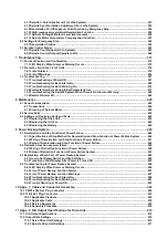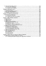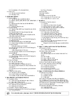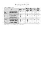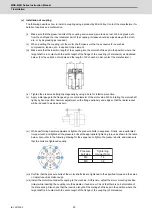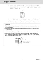
MDS-E/EH Series Instruction Manual
1 Installation
7
IB-1501229-F
1.1.7 Coupling with the Load
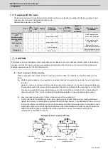
There are several ways to couple the motor shaft and machine, such as direct coupling with flexible coupling or rigid
coupling, gear connection, timing belt connection, etc.
Summarized comparison is as follows.
(1) Direct coupling - Flexible coupling
When coupling the load directly, a flexible coupling is recommended. The benefits of a flexible coupling are as
below.
(a) Shaft's angle deviation and core deviation can be absorbed to some extent, so adjustment in motor installation
is easier.
However, in the case of single, shaft core deviation cannot be allowed, so it is required to design and adjust so
that the shaft cores of the motor and ball screw align. Check the specification of the coupling to use. If the shaft
core deviation exceeds the coupling's tolerable level, the motor will have a broken shaft, or the bearing will
have a shorter life. Thus, in order to simplify the installation adjustment, use a double flexible coupling.
(b) Less looseness produces less vibration and less noise at the coupling part.
On the other hand, if assembling is loose, lower rigidity may be caused. When using a coupling with lower
rigidity, the accuracy in centering the core doesn't have to be high, however, it is undesirable for servo. In order
to fully utilize the servo's efficiency to ensure the maximum durability of the equipments, it is required to use a
highly rigid coupling, and to fully align the shaft cores in the initial installation. It is also required to select the
optimum flexible coupling according to the working conditions, and use it correctly according to the
manufacturer's specification manual.
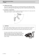
Example of direct coupling with load
Noise
No
lubric
ation
Backl
ash
Rigidity
Reliability
in coupling
Life
Torque
increased at
deceleration
Degree of
freedom in
motor
installation
Cautions in motor
installation
Direct coupling
with
flexible coupling
◯
◯
◯
◯
◯
Looseness of bolt
◯
×
△
Shaft core deviation
(In the case of single)
Direct coupling
with
rigid coupling
◯
◯
◯
◯
◯
Looseness of bolt
◯
×
×
Shaft core deviation
Angle deviation
Gear
×
×
△
△
△
Tooth chipping
△
◯
◯
Backlash too small
Pitch diameter too small
Timing belt
△
◯
◯
×
×
Belt is broken
×
◯
◯
Belt stretched too much
Pitch diameter too small
CAUTION
If the cautions in motor installation in the above table are not observed, the motor will have a broken shaft, or the bearing
will have a shorter life. Carry out design and installation adjustment so that the load on the motor shaft will be below the
tolerable loads mentioned in "Shaft Characteristics".
Load shaft
Spun ring
Flexible coupling
Motor shaft
Load shaft
Spun ring
Flexible coupling
Motor shaft
(a) Taper shaft
(b) Straight shaft
Summary of Contents for MDS-E
Page 1: ......
Page 3: ......
Page 15: ......
Page 17: ......
Page 19: ......
Page 21: ......
Page 31: ......
Page 32: ...1 IB 1501229 F 1 Installation ...
Page 76: ...45 IB 1501229 F 2 Wiring and Connection ...
Page 132: ...101 IB 1501229 F 3 Safety Function ...
Page 142: ...111 IB 1501229 F 4 Setup ...
Page 277: ...MDS E EH Series Instruction Manual 4 Setup 246 IB 1501229 F ...
Page 278: ...247 IB 1501229 F 5 Servo Adjustment ...
Page 351: ...MDS E EH Series Instruction Manual 5 Servo Adjustment 320 IB 1501229 F ...
Page 352: ...321 IB 1501229 F 6 Spindle Adjustment ...
Page 404: ...373 IB 1501229 F 7 Troubleshooting ...
Page 455: ...MDS E EH Series Instruction Manual 7 Troubleshooting 424 IB 1501229 F ...
Page 456: ...425 IB 1501229 F 8 Maintenance ...
Page 475: ...MDS E EH Series Instruction Manual 8 Maintenance 444 IB 1501229 F ...
Page 476: ...445 IB 1501229 F 9 Power Backup System ...
Page 494: ...463 IB 1501229 F 10 Appx 1 Cable and Connector Assembly ...
Page 504: ...473 IB 1501229 F 11 Appx 2 D A Output Specifications for Drive Unit ...
Page 514: ...483 IB 1501229 F 12 Appx 3 Protection Function ...
Page 523: ...MDS E EH Series Instruction Manual 12 Appx 3 Protection Function 492 IB 1501229 F ...
Page 524: ...493 IB 1501229 F 13 Appx 4 Compliance to EC Directives ...
Page 528: ...497 IB 1501229 F 14 Appx 5 EMC Installation Guidelines ...
Page 540: ...509 IB 1501229 F 15 Appx 6 Higher Harmonic Suppression Measure Guidelines ...
Page 550: ......
Page 554: ......

