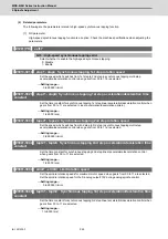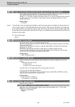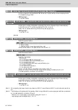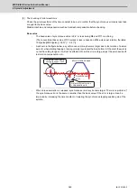
MDS-E/EH Series Instruction Manual
6 Spindle Adjustment
352
IB-1501229-F
6.1.8 Spindle Synchronization Adjustment (For Lathe System)
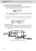
(1) Setting the gain, changeover rotation speed and time constant
[1] For speed loop gain during spindle synchronization, SP005 (speed loop gain 1), SP006 (speed loop lead
compensation 1), and SP007 (speed loop delay compensation 2) are used. For position loop gain, set
standard 15 to SP003 (position loop gain spindle synchronization).
(Note1) To change the setting value of SP003, set the synchronous and basic spindles to the same value.
(Note2)
For the adjustment of SP005, SP006 and SP007, conduct "Adjusting the speed loop parameter" as
a single unit beforehand.
[2] Set rotation speed and time constant during acceleration/deceleration figured by theoretical calculations.
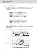
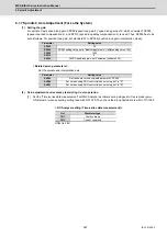
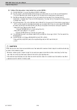
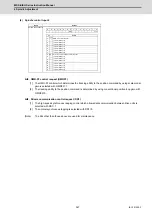
[3] Set "Time-series data measurement" with NC Analyzer as follows and output speed feedback and current
command.
< NC Analyzer setting (Time-series data measurement) >
(2) Confirming the current margin
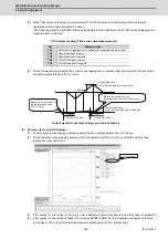
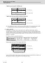
Perform acceleration/deceleration up to the maximum current speed in spindle synchronization mode. At this time,
confirm that the current value for both acceleration side and deceleration side secure 30% or more of margin in
respect to the current limit value. Also, confirm that no oscillation, etc. are found in the current waveforms.
(Note)
If a margin is 30% or less, extend the acceleration/deceleration time constant so that the margin is
adjusted to 30% or more.
Output waveform example in spindle synchronous mode
Parameter
Setting value
SP003
15
SP036
0000
Get
Waveform type
CH1
Speed feedback (r/min)
CH2
Current command
0
0
Current margin has to
be 30% or more.
Current margin has to be
30% or more.
SP152 or SP186
Speed feedback
Current command
SP153 or SP185
Current limit at accelaration
Current limit at regeneration
Summary of Contents for MDS-E
Page 1: ......
Page 3: ......
Page 15: ......
Page 17: ......
Page 19: ......
Page 21: ......
Page 31: ......
Page 32: ...1 IB 1501229 F 1 Installation ...
Page 76: ...45 IB 1501229 F 2 Wiring and Connection ...
Page 132: ...101 IB 1501229 F 3 Safety Function ...
Page 142: ...111 IB 1501229 F 4 Setup ...
Page 277: ...MDS E EH Series Instruction Manual 4 Setup 246 IB 1501229 F ...
Page 278: ...247 IB 1501229 F 5 Servo Adjustment ...
Page 351: ...MDS E EH Series Instruction Manual 5 Servo Adjustment 320 IB 1501229 F ...
Page 352: ...321 IB 1501229 F 6 Spindle Adjustment ...
Page 404: ...373 IB 1501229 F 7 Troubleshooting ...
Page 455: ...MDS E EH Series Instruction Manual 7 Troubleshooting 424 IB 1501229 F ...
Page 456: ...425 IB 1501229 F 8 Maintenance ...
Page 475: ...MDS E EH Series Instruction Manual 8 Maintenance 444 IB 1501229 F ...
Page 476: ...445 IB 1501229 F 9 Power Backup System ...
Page 494: ...463 IB 1501229 F 10 Appx 1 Cable and Connector Assembly ...
Page 504: ...473 IB 1501229 F 11 Appx 2 D A Output Specifications for Drive Unit ...
Page 514: ...483 IB 1501229 F 12 Appx 3 Protection Function ...
Page 523: ...MDS E EH Series Instruction Manual 12 Appx 3 Protection Function 492 IB 1501229 F ...
Page 524: ...493 IB 1501229 F 13 Appx 4 Compliance to EC Directives ...
Page 528: ...497 IB 1501229 F 14 Appx 5 EMC Installation Guidelines ...
Page 540: ...509 IB 1501229 F 15 Appx 6 Higher Harmonic Suppression Measure Guidelines ...
Page 550: ......
Page 554: ......

