MDS-E/EH Series Instruction Manual
6 Spindle Adjustment
359
IB-1501229-F
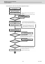
< How to adjust the spindle motor temperature compensation function >
YES
NO
YES
NO
YES
NO
YES
NO
Start the adjustment
Change SP153 and SP185 to [original setting x 0.8]
respectively.
(Note) Turn OFF/ON the NC power after this change.
[Cycle counter] on the
spindle monitor is ≠0?
Stop the spindle (servo OFF)
Set the temperature compensation
parameters to the initial settings:
SP235(R2H)=150, SP236(WIH)=0
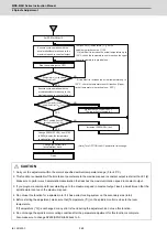
Change the current limit (acceleration)
Forward-run the spindle
(command speed at approx. 60r/min)
For the initial operation after setting SP226/bit8 = 1,
make sure to perform acceleration/deceleration that
reaches the maximum rotation speed in constant output.
If the acceleration/deceleration has not reached
the maximum speed, set SP226/bit8=0 once,
and then SP226/bit8=1. This resets the display.
[AFLT gain(dB)] on the
spindle monitor is
≦
110?
Decrement SP235(R2H) by 5
* The lower limit of setting is 100.
[AFLT gain(dB)] on the
spindle monitor is
≧
90?
[Temperature] on the spindle
monitor is
≧
100?
* If you reduce SP235(R2H) too much, excessive
compensation will result and [AFLT gain (dB)] will be too
high. In this case increment the setting by 5.
Increment SP235(R2H) by 5
Stop the spindle (servo OFF)
* If it is difficult to increase the actual temperature up to
100
°C
, check the temperature until it reaches the upper
limit of temperature in practical use.
Adjusting SP235(R2H) is complete.
Change SP226(SFNC6) from 0000 to
0100 (display the temperature
compensation adjustment indicator)
Execute cycle operation with the
acceleration/deceleration up to the
maximum speed in constant output
Summary of Contents for MDS-E
Page 1: ......
Page 3: ......
Page 15: ......
Page 17: ......
Page 19: ......
Page 21: ......
Page 31: ......
Page 32: ...1 IB 1501229 F 1 Installation ...
Page 76: ...45 IB 1501229 F 2 Wiring and Connection ...
Page 132: ...101 IB 1501229 F 3 Safety Function ...
Page 142: ...111 IB 1501229 F 4 Setup ...
Page 277: ...MDS E EH Series Instruction Manual 4 Setup 246 IB 1501229 F ...
Page 278: ...247 IB 1501229 F 5 Servo Adjustment ...
Page 351: ...MDS E EH Series Instruction Manual 5 Servo Adjustment 320 IB 1501229 F ...
Page 352: ...321 IB 1501229 F 6 Spindle Adjustment ...
Page 404: ...373 IB 1501229 F 7 Troubleshooting ...
Page 455: ...MDS E EH Series Instruction Manual 7 Troubleshooting 424 IB 1501229 F ...
Page 456: ...425 IB 1501229 F 8 Maintenance ...
Page 475: ...MDS E EH Series Instruction Manual 8 Maintenance 444 IB 1501229 F ...
Page 476: ...445 IB 1501229 F 9 Power Backup System ...
Page 494: ...463 IB 1501229 F 10 Appx 1 Cable and Connector Assembly ...
Page 504: ...473 IB 1501229 F 11 Appx 2 D A Output Specifications for Drive Unit ...
Page 514: ...483 IB 1501229 F 12 Appx 3 Protection Function ...
Page 523: ...MDS E EH Series Instruction Manual 12 Appx 3 Protection Function 492 IB 1501229 F ...
Page 524: ...493 IB 1501229 F 13 Appx 4 Compliance to EC Directives ...
Page 528: ...497 IB 1501229 F 14 Appx 5 EMC Installation Guidelines ...
Page 540: ...509 IB 1501229 F 15 Appx 6 Higher Harmonic Suppression Measure Guidelines ...
Page 550: ......
Page 554: ......

