
MDS-E/EH Series Instruction Manual
6 Spindle Adjustment
362
IB-1501229-F
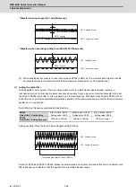
6.2 Settings for Emergency Stop
Emergency stop in this section refers to the following states.
[1] Emergency stop was input (including other axis alarms)
[2] NC power down was detected
[3] A drive unit alarm was detected
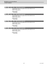
6.2.1 Deceleration Control
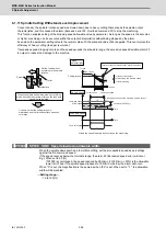
(1) Setting the deceleration control time constant
Set the time for stopping from the maximum motor speed (TSP) in the deceleration time constant for emergency
stop (SV056: EMGt). When "0" is set, the deceleration stop is executed with "7000ms".
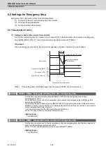
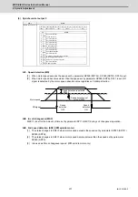
<Operation>
When an emergency stop occurs, the motor will decelerate at the same inclination from each speed.
(Note)
If the setting value of SP056 is longer than the value of SP055, the motor will coast.
【
#13055
】
SP055 EMGx Max. gate off delay time after emergency stop
Set the time required to forcibly execute READY OFF after the emergency stop is input.
Normally set to "5000".
When 5000ms or more is set for deceleration time constant at emergency stop (SP056), set the
same value as SP056.
When using the power backup system (MDS-D/DH-PFU) and setting the value of this parameter to
5000ms or more, a communication error between NC and drive unit may occur when power restarts
after a instantaneous power interrupt.
It is not a problem so turn the NC power ON again to start up.
When "0" is set, 7000ms is the actual value to be set.
---Setting range---
0 to 29900 (ms)
【
#13056
】
SP056 EMGt Deceleration time constant at emergency stop
Set the time constant used for the deceleration control at emergency stop. Set the time required to
stop from the maximum motor speed (TSP).
When "0" is set, the deceleration control is executed with "7000ms".
---Setting range---
0 to 29900 (ms)
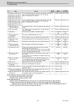
ON
OFF
ON
ON
TSP
SP056
SP055
(EMG)
(ZSP)
(READY)
OFF
OFF
Forced READY OFF range
Constant inclination
deceleration
Motor speed
Time
Deceleration control sequence
Emergency stop
Servo READY
Zero speed
Summary of Contents for MDS-E
Page 1: ......
Page 3: ......
Page 15: ......
Page 17: ......
Page 19: ......
Page 21: ......
Page 31: ......
Page 32: ...1 IB 1501229 F 1 Installation ...
Page 76: ...45 IB 1501229 F 2 Wiring and Connection ...
Page 132: ...101 IB 1501229 F 3 Safety Function ...
Page 142: ...111 IB 1501229 F 4 Setup ...
Page 277: ...MDS E EH Series Instruction Manual 4 Setup 246 IB 1501229 F ...
Page 278: ...247 IB 1501229 F 5 Servo Adjustment ...
Page 351: ...MDS E EH Series Instruction Manual 5 Servo Adjustment 320 IB 1501229 F ...
Page 352: ...321 IB 1501229 F 6 Spindle Adjustment ...
Page 404: ...373 IB 1501229 F 7 Troubleshooting ...
Page 455: ...MDS E EH Series Instruction Manual 7 Troubleshooting 424 IB 1501229 F ...
Page 456: ...425 IB 1501229 F 8 Maintenance ...
Page 475: ...MDS E EH Series Instruction Manual 8 Maintenance 444 IB 1501229 F ...
Page 476: ...445 IB 1501229 F 9 Power Backup System ...
Page 494: ...463 IB 1501229 F 10 Appx 1 Cable and Connector Assembly ...
Page 504: ...473 IB 1501229 F 11 Appx 2 D A Output Specifications for Drive Unit ...
Page 514: ...483 IB 1501229 F 12 Appx 3 Protection Function ...
Page 523: ...MDS E EH Series Instruction Manual 12 Appx 3 Protection Function 492 IB 1501229 F ...
Page 524: ...493 IB 1501229 F 13 Appx 4 Compliance to EC Directives ...
Page 528: ...497 IB 1501229 F 14 Appx 5 EMC Installation Guidelines ...
Page 540: ...509 IB 1501229 F 15 Appx 6 Higher Harmonic Suppression Measure Guidelines ...
Page 550: ......
Page 554: ......


