
MDS-E/EH Series Instruction Manual
6 Spindle Adjustment
363
IB-1501229-F
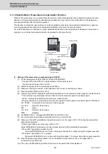
6.3 Spindle Control Signal
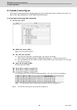
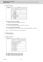
The sequence input/output signals exchanged between the NC and spindle drive unit are explained in this section. The
status of each signal is displayed on the NC SPINDLE MONITOR screen.
6.3.1 Spindle Control Input (NC to Spindle)
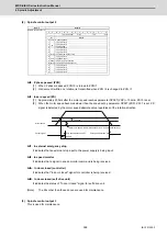
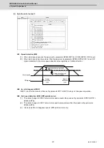
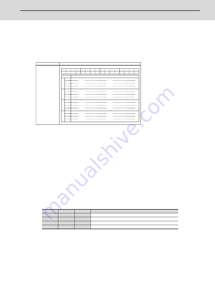
(1) Spindle control input 1
bit0. READY ON command (RDY)
Status turns to ready ON at RDY=1.
bit1. Servo ON command (SRV)
[1] Drive unit turns ON at SRV=1 (gate ON status), and rotation control starts.
Plus or minus of the rotation direction is determined depending on +/- of the NC command F
Δ
T.
[2] Servo immediately turns OFF (SON=0) at SRV=0 during rotation control. Drive unit also turns OFF (gate
OFF status) at this time.
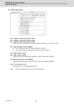
bit7. Alarm reset command (ALMR)
NR alarm is reset at ALMR=1.
bit8. Torque limit 1 selection command (TL1)
bit9. Torque limit 2 selection command (TL2)
bitA. Torque limit 3 selection command (TL3)
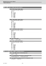
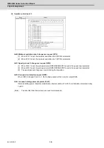
The following 4 types of torque limit are available depending on TL1, TL2 and TL3 bit combinations.
(Note)
The ratio to motor short time rated torque (load meter 100%) is indicated in %.
(Note)
The bits other than those above are used for maintenance.
TL3
TL2
TL1
Torque limit value
0
0
1
Torque limit value (%) set with parameter SP065
0
1
0
Torque limit value (%) set with parameter SP066
0
1
1
Torque limit value (%) set with parameter SP067
1
0
0
Torque limit value (%) set with parameter SP068
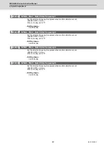
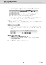
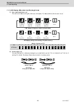
Name Details
Spindle control input 1
F E D C B A 9 8 7 6 5 4 3 2 1 0
TL3
TL2
TL1
ALMR
SRV RDY
bit
Details
0
RDY
READY ON command
1
SRV
Servo ON command
2
- (For
maintenance)
3
-
(For maintenance)
4
-
(For maintenance)
5
-
(For maintenance)
6
-
(For maintenance)
7
ALMR
Alarm reset command
8
TL1
Torque limit 1 selection command
9
TL2
Torque limit 2 selection command
A
TL3
Torque limit 3 selection command
B
-
(For maintenance)
C
-
(For maintenance)
D
-
(For maintenance)
E
-
(For maintenance)
F
-
(For maintenance)
Summary of Contents for MDS-E
Page 1: ......
Page 3: ......
Page 15: ......
Page 17: ......
Page 19: ......
Page 21: ......
Page 31: ......
Page 32: ...1 IB 1501229 F 1 Installation ...
Page 76: ...45 IB 1501229 F 2 Wiring and Connection ...
Page 132: ...101 IB 1501229 F 3 Safety Function ...
Page 142: ...111 IB 1501229 F 4 Setup ...
Page 277: ...MDS E EH Series Instruction Manual 4 Setup 246 IB 1501229 F ...
Page 278: ...247 IB 1501229 F 5 Servo Adjustment ...
Page 351: ...MDS E EH Series Instruction Manual 5 Servo Adjustment 320 IB 1501229 F ...
Page 352: ...321 IB 1501229 F 6 Spindle Adjustment ...
Page 404: ...373 IB 1501229 F 7 Troubleshooting ...
Page 455: ...MDS E EH Series Instruction Manual 7 Troubleshooting 424 IB 1501229 F ...
Page 456: ...425 IB 1501229 F 8 Maintenance ...
Page 475: ...MDS E EH Series Instruction Manual 8 Maintenance 444 IB 1501229 F ...
Page 476: ...445 IB 1501229 F 9 Power Backup System ...
Page 494: ...463 IB 1501229 F 10 Appx 1 Cable and Connector Assembly ...
Page 504: ...473 IB 1501229 F 11 Appx 2 D A Output Specifications for Drive Unit ...
Page 514: ...483 IB 1501229 F 12 Appx 3 Protection Function ...
Page 523: ...MDS E EH Series Instruction Manual 12 Appx 3 Protection Function 492 IB 1501229 F ...
Page 524: ...493 IB 1501229 F 13 Appx 4 Compliance to EC Directives ...
Page 528: ...497 IB 1501229 F 14 Appx 5 EMC Installation Guidelines ...
Page 540: ...509 IB 1501229 F 15 Appx 6 Higher Harmonic Suppression Measure Guidelines ...
Page 550: ......
Page 554: ......


