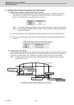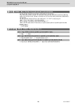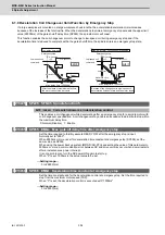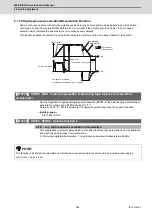
MDS-E/EH Series Instruction Manual
6 Spindle Adjustment
366
IB-1501229-F
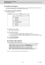
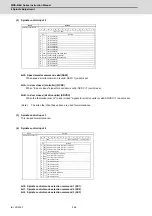
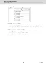
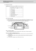
(5) Spindle control input 5
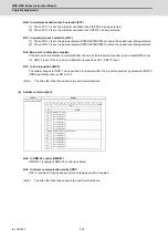
bitB. Minimum excitation rate 2 changeover request (PY2)
[1] When PY2=1 is set, the minimum excitation rate 2 (SP015) is selected.
[2] When PY2=0 is set, the minimum excitation rate 1 (SP014) is selected.
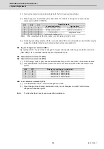
bitC. Speed gain set 2 changeover request (VG2)
[1] When VG2=1 is set, the gain parameter (SP008/SP009/SP010) used in the speed loop isselected.
[2] When VG2=0 is set, the gain parameter (SP005/SP006/SP007) used in the speed loop isselected.
[3] The speed gain set changeover is valid during the in-position.
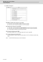
bitD. Zero point re-detection request (ORC)
When ORC is changed from 0 to 1, the Z phase passed will be 0 (control output2/bit0).
bitE. Increase holding power of spindle (TLUP)
Increase holding power of spindle (disturbance observer) starts at TLUP=1 and that state is retained during
TLUP=1.
(Note)
The bits other than those above are used for maintenance.
F
E
D
C
B
A
9
8
7
6
5
4
3
2
1
0
bit
0
1
2
3
4
5
6
7
8
9
A
B
C
D
E
F
-
-
-
-
VG2
ORC
-
ORC
TLUP
TLUP
VG2
PY2
PY2
-
-
-
-
-
-
-
Details
Name
Details
Spindle control input 5
(For maintenance)
(For maintenance)
(For maintenance)
Zero point re-detection request
(For maintenance)
Increase holding power of spindle
(For maintenance)
(For maintenance)
(For maintenance)
(For maintenance)
(For maintenance)
(For maintenance)
(For maintenance)
Minimum excitation rate 2 changeover request
Speed gain set 2 changeover request
(For maintenance)
Summary of Contents for MDS-E
Page 1: ......
Page 3: ......
Page 15: ......
Page 17: ......
Page 19: ......
Page 21: ......
Page 31: ......
Page 32: ...1 IB 1501229 F 1 Installation ...
Page 76: ...45 IB 1501229 F 2 Wiring and Connection ...
Page 132: ...101 IB 1501229 F 3 Safety Function ...
Page 142: ...111 IB 1501229 F 4 Setup ...
Page 277: ...MDS E EH Series Instruction Manual 4 Setup 246 IB 1501229 F ...
Page 278: ...247 IB 1501229 F 5 Servo Adjustment ...
Page 351: ...MDS E EH Series Instruction Manual 5 Servo Adjustment 320 IB 1501229 F ...
Page 352: ...321 IB 1501229 F 6 Spindle Adjustment ...
Page 404: ...373 IB 1501229 F 7 Troubleshooting ...
Page 455: ...MDS E EH Series Instruction Manual 7 Troubleshooting 424 IB 1501229 F ...
Page 456: ...425 IB 1501229 F 8 Maintenance ...
Page 475: ...MDS E EH Series Instruction Manual 8 Maintenance 444 IB 1501229 F ...
Page 476: ...445 IB 1501229 F 9 Power Backup System ...
Page 494: ...463 IB 1501229 F 10 Appx 1 Cable and Connector Assembly ...
Page 504: ...473 IB 1501229 F 11 Appx 2 D A Output Specifications for Drive Unit ...
Page 514: ...483 IB 1501229 F 12 Appx 3 Protection Function ...
Page 523: ...MDS E EH Series Instruction Manual 12 Appx 3 Protection Function 492 IB 1501229 F ...
Page 524: ...493 IB 1501229 F 13 Appx 4 Compliance to EC Directives ...
Page 528: ...497 IB 1501229 F 14 Appx 5 EMC Installation Guidelines ...
Page 540: ...509 IB 1501229 F 15 Appx 6 Higher Harmonic Suppression Measure Guidelines ...
Page 550: ......
Page 554: ......

