MDS-E/EH Series Instruction Manual
6 Spindle Adjustment
369
IB-1501229-F
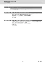
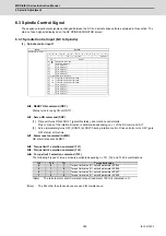
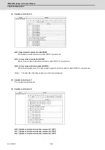
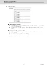
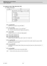
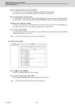
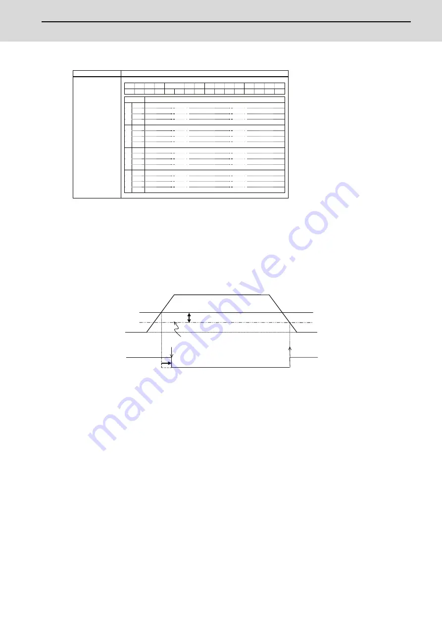
(2) Spindle control output 2
bit0. Z phase passed (ZCN)
[1] When Z phase is passed, ZCN=0 is turned to ZCN=1.
[2] Grid amount (within one rotation) is transmitted when ZCN =0 is changed to ZCN =1.
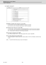
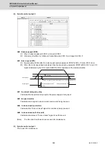
bit3. In zero speed (ZS)
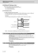
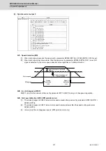
[1] Approximately 200ms after the motor speed reaches parameter SP027 (ZSP) + 15r/min, ZS=0 is set.
[2] When the motor speed becomes slower than the speed set by parameter SP027 (ZSP), ZS=1 is set. ZS
signal is detected by the motor speed absolute value regardless of the rotation direction.
bit7. In external emergency stop
It indicates that an external stop input to the power supply is being input.
bit9. In speed monitor
It indicates that a signal in speed monitor command is being received.
bitA. In door closed (controller)
It indicates that "In door closed" signal for controller is being received.
bitB. In door closed (self drive unit)
It indicates the status of "In door closed" signal for self drive unit.
(Note)
The bits other than those above are used for maintenance.
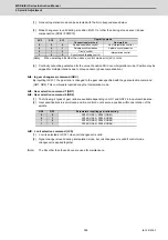
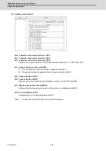
(3) Spindle control output 3
This is used for maintenance.
Name
Details
Spindle control output 2
F
E
D
C
B
A
9
8
7
6
5
4
3
2
1
0
SRVDC
NCDC SSW
EXEMG
ZS
ZCN
bit
Details
0
ZCN
Z phase passed
1
-
(For maintenance)
2
-
(For maintenance)
3
ZS
In zero speed
4
-
(For maintenance)
5
-
(For maintenance)
6
-
(For maintenance)
7
EXEMG
In external emergency stop
8
-
(For maintenance)
9
SSW
In speed monitor
A
NCDC
In door closed (controller)
B
SRVDC
In door closed (self drive unit)
C
-
(For maintenance)
D
-
(For maintenance)
E
-
(For maintenance)
F
-
(For maintenance)
Motor speed
Motor zero speed: SP027(Standard 50r/min Sub-standard 25r/min)
Output signal
Zero speed detection OFF
Zero speed detection ON
+ 15r/min
200ms
Summary of Contents for MDS-E
Page 1: ......
Page 3: ......
Page 15: ......
Page 17: ......
Page 19: ......
Page 21: ......
Page 31: ......
Page 32: ...1 IB 1501229 F 1 Installation ...
Page 76: ...45 IB 1501229 F 2 Wiring and Connection ...
Page 132: ...101 IB 1501229 F 3 Safety Function ...
Page 142: ...111 IB 1501229 F 4 Setup ...
Page 277: ...MDS E EH Series Instruction Manual 4 Setup 246 IB 1501229 F ...
Page 278: ...247 IB 1501229 F 5 Servo Adjustment ...
Page 351: ...MDS E EH Series Instruction Manual 5 Servo Adjustment 320 IB 1501229 F ...
Page 352: ...321 IB 1501229 F 6 Spindle Adjustment ...
Page 404: ...373 IB 1501229 F 7 Troubleshooting ...
Page 455: ...MDS E EH Series Instruction Manual 7 Troubleshooting 424 IB 1501229 F ...
Page 456: ...425 IB 1501229 F 8 Maintenance ...
Page 475: ...MDS E EH Series Instruction Manual 8 Maintenance 444 IB 1501229 F ...
Page 476: ...445 IB 1501229 F 9 Power Backup System ...
Page 494: ...463 IB 1501229 F 10 Appx 1 Cable and Connector Assembly ...
Page 504: ...473 IB 1501229 F 11 Appx 2 D A Output Specifications for Drive Unit ...
Page 514: ...483 IB 1501229 F 12 Appx 3 Protection Function ...
Page 523: ...MDS E EH Series Instruction Manual 12 Appx 3 Protection Function 492 IB 1501229 F ...
Page 524: ...493 IB 1501229 F 13 Appx 4 Compliance to EC Directives ...
Page 528: ...497 IB 1501229 F 14 Appx 5 EMC Installation Guidelines ...
Page 540: ...509 IB 1501229 F 15 Appx 6 Higher Harmonic Suppression Measure Guidelines ...
Page 550: ......
Page 554: ......

