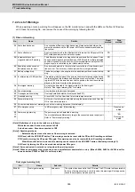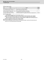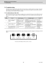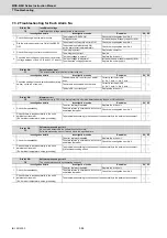
MDS-E/EH Series Instruction Manual
7 Troubleshooting
374
IB-1501229-F
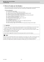
7.1 Points of Caution and Confirmation
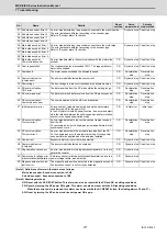
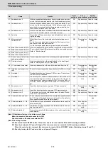
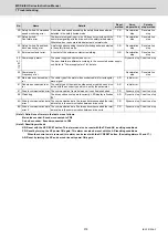
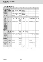
If an error occurs in the drive unit, the warning or alarm will occur. When a warning or alarm occurs, check the state while
observing the following points, and inspect or remedy the unit according to the details given in this section.
< Points of confirmation >
[1] What is the alarm code display?
[2] Can the error or trouble be repeated? (Check alarm history)
[3] Is the motor and servo drive unit temperature and ambient temperature normal?
[4] Are the servo drive unit, control unit and motor grounded?
[5] Was the unit accelerating, decelerating or running at a set speed? What was the speed?
[6] Is there any difference during forward and backward run?
[7] Was there a momentary power failure?
[8] Did the trouble occur during a specific operation or command?
[9] At what frequency does the trouble occur?
[10] Is a load applied or removed?
[11] Has the drive unit been replaced, parts replaced or emergency measures taken?
[12] How many years has the unit been operating?
[13] Is the power supply voltage normal? Does the state change greatly according to the time band?
CAUTION
1. This power supply unit uses a large capacity electrolytic capacitor. When the CHARGE lamp on the front of the power
supply unit is lit, voltage is still present at the PN terminal (TE2). Do not touch the terminal block in this state.
2. Before replacing the unit, etc., always confirm that there is no voltage at the PN terminal (TE2) with a tester or wait at
least 15 minutes after turning the main power OFF.
3. The conductivity in the unit cannot be checked.
4. Never carry out a megger test on the drive unit or power supply unit as the unit could be damaged.
POINT
When the drive unit of E/EH Series which uses two cooling fans is in an emergency stop or alarm, one of fans (upper one in
the case of vertical layout, or either one in the case of horizontal layout) is stopped and power-saving operation is
performed. If the suspended fan is restarted by canceling the emergency stop, it is not a problem with the fan.
Summary of Contents for MDS-E
Page 1: ......
Page 3: ......
Page 15: ......
Page 17: ......
Page 19: ......
Page 21: ......
Page 31: ......
Page 32: ...1 IB 1501229 F 1 Installation ...
Page 76: ...45 IB 1501229 F 2 Wiring and Connection ...
Page 132: ...101 IB 1501229 F 3 Safety Function ...
Page 142: ...111 IB 1501229 F 4 Setup ...
Page 277: ...MDS E EH Series Instruction Manual 4 Setup 246 IB 1501229 F ...
Page 278: ...247 IB 1501229 F 5 Servo Adjustment ...
Page 351: ...MDS E EH Series Instruction Manual 5 Servo Adjustment 320 IB 1501229 F ...
Page 352: ...321 IB 1501229 F 6 Spindle Adjustment ...
Page 404: ...373 IB 1501229 F 7 Troubleshooting ...
Page 455: ...MDS E EH Series Instruction Manual 7 Troubleshooting 424 IB 1501229 F ...
Page 456: ...425 IB 1501229 F 8 Maintenance ...
Page 475: ...MDS E EH Series Instruction Manual 8 Maintenance 444 IB 1501229 F ...
Page 476: ...445 IB 1501229 F 9 Power Backup System ...
Page 494: ...463 IB 1501229 F 10 Appx 1 Cable and Connector Assembly ...
Page 504: ...473 IB 1501229 F 11 Appx 2 D A Output Specifications for Drive Unit ...
Page 514: ...483 IB 1501229 F 12 Appx 3 Protection Function ...
Page 523: ...MDS E EH Series Instruction Manual 12 Appx 3 Protection Function 492 IB 1501229 F ...
Page 524: ...493 IB 1501229 F 13 Appx 4 Compliance to EC Directives ...
Page 528: ...497 IB 1501229 F 14 Appx 5 EMC Installation Guidelines ...
Page 540: ...509 IB 1501229 F 15 Appx 6 Higher Harmonic Suppression Measure Guidelines ...
Page 550: ......
Page 554: ......

