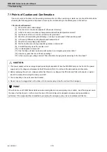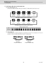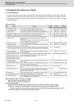
MDS-E/EH Series Instruction Manual
7 Troubleshooting
379
IB-1501229-F
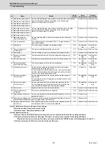
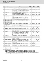
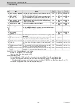
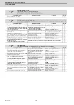
(Note 1) Definitions of terms in the table are as follows.
Main side encoder: Encoder connected to CN2
Sub side encoder: Encoder connected to CN3
(Note 2) Resetting methods
NR: Reset with the NC RESET button. This alarm can also be reset with the PR and AR resetting conditions.
PR: Reset by turning the NC power ON again. This alarm can also be reset with the AR resetting conditions.
When the control axis is removed, this alarm can be reset with the NC RESET button. (Excluding alarms 32 and 37.)
AR: Reset by turning the NC and servo drive unit power ON again.
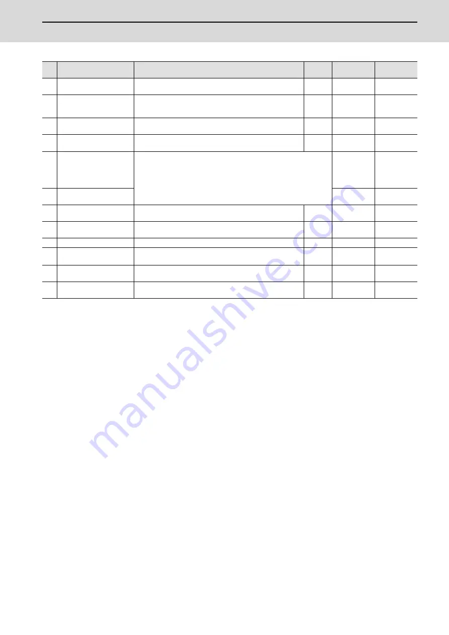
No.
Name
Details
Reset
method
Servo
stop method
Spindle
stop method
5B Safely limited: Commanded
speed monitoring error
A commanded speed exceeding the safely limited speed was
detected in the safely limited mode.
PR
Deceleration
stop
Deceleration
stop
5D Safely limited:
Door state error
The door state signal input in the NC does not coincide with the
door state signal input in the drive unit in the safely limited mode.
Otherwise, door open state was detected in normal mode.
PR
Deceleration
stop
Deceleration
stop
5E Safely limited: Speed feed-
back monitoring error
A motor speed exceeding the safely limited speed was detected
in the safely limited mode.
PR
Deceleration
stop
Deceleration
stop
5F External contactor error
A contact of the external contactor is welding.
NR
Deceleration
stop
Deceleration
stop
60,
61,
63
to
77
Power supply alarm
The power supply unit detected an error.
The error details are different according to the connected power supply
unit. Refer to "Power supply alarm" for details.
Dynamic stop Coast to a stop
62 Power supply:
Frequency error
Deceleration
stop
Deceleration
stop
80 Main side encoder cable er-
ror
The cable type of the motor side encoder cable is for rectangular
wave signal.
AR
Initial error
-
81 Sub side encoder cable er-
ror
The cable type of the machine side encoder cable does not co-
incide with the encoder type which is set by the parameter.
AR
Initial error
-
87 Drivers communication error The communication frame between drive units was aborted.
PR
Dynamic stop Coast to a stop
88 Watchdog
The drive unit does not operate correctly. LED display is fixed as
"88".
AR
Dynamic stop Coast to a stop
8A Drivers communication data
error 1
The communication data 1 between drivers exceeded the toler-
able value in the communication between drive units.
PR
Dynamic stop Coast to a stop
8B Drivers communication data
error 2
The communication data 2 between drivers exceeded the toler-
able value in the communication between drive units.
PR
Dynamic stop Coast to a stop
Summary of Contents for MDS-E
Page 1: ......
Page 3: ......
Page 15: ......
Page 17: ......
Page 19: ......
Page 21: ......
Page 31: ......
Page 32: ...1 IB 1501229 F 1 Installation ...
Page 76: ...45 IB 1501229 F 2 Wiring and Connection ...
Page 132: ...101 IB 1501229 F 3 Safety Function ...
Page 142: ...111 IB 1501229 F 4 Setup ...
Page 277: ...MDS E EH Series Instruction Manual 4 Setup 246 IB 1501229 F ...
Page 278: ...247 IB 1501229 F 5 Servo Adjustment ...
Page 351: ...MDS E EH Series Instruction Manual 5 Servo Adjustment 320 IB 1501229 F ...
Page 352: ...321 IB 1501229 F 6 Spindle Adjustment ...
Page 404: ...373 IB 1501229 F 7 Troubleshooting ...
Page 455: ...MDS E EH Series Instruction Manual 7 Troubleshooting 424 IB 1501229 F ...
Page 456: ...425 IB 1501229 F 8 Maintenance ...
Page 475: ...MDS E EH Series Instruction Manual 8 Maintenance 444 IB 1501229 F ...
Page 476: ...445 IB 1501229 F 9 Power Backup System ...
Page 494: ...463 IB 1501229 F 10 Appx 1 Cable and Connector Assembly ...
Page 504: ...473 IB 1501229 F 11 Appx 2 D A Output Specifications for Drive Unit ...
Page 514: ...483 IB 1501229 F 12 Appx 3 Protection Function ...
Page 523: ...MDS E EH Series Instruction Manual 12 Appx 3 Protection Function 492 IB 1501229 F ...
Page 524: ...493 IB 1501229 F 13 Appx 4 Compliance to EC Directives ...
Page 528: ...497 IB 1501229 F 14 Appx 5 EMC Installation Guidelines ...
Page 540: ...509 IB 1501229 F 15 Appx 6 Higher Harmonic Suppression Measure Guidelines ...
Page 550: ......
Page 554: ......

