
MDS-E/EH Series Instruction Manual
7 Troubleshooting
385
IB-1501229-F
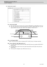
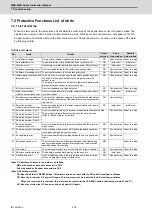
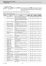
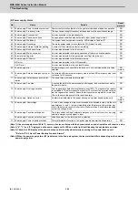
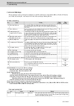
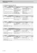
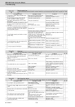
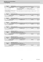
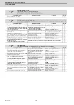
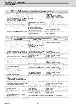
7.2.2 List of Warnings
When a warning occurs, a warning No. will appear on the NC monitor screen and with the LEDs on the front of the drive
unit. Check the warning No., and remove the cause of the warning by following this list.
(1) Drive unit warning
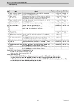
(Note1) Definitions of terms in the table are as follows.
Main side encoder: Encoder connected to CN2
Sub side encoder: Encoder connected to CN3
(Note 2) Resetting methods
* : Automatically reset once the cause of the warning is removed.
NR: Reset with the NC RESET button. This warning can also be reset with the PR and AR resetting conditions.
PR: Reset by turning the NC power ON again. This warning can also be reset with the AR resetting conditions.
When the control axis is removed, this warning can be reset with the NC RESET button. (Excluding warning 93.)
AR: Reset by turning the NC and servo drive unit power ON again.
(Note 3) Servo and spindle motor do not stop when the warning occurs.
(Note 4) When an emergency stop is input, servo and spindle motor decelerate to a stop. (When SV048, SV055 or SV056 is set for
servo and when SP055 or SP056 is set for spindle.)
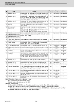
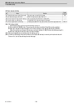
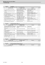
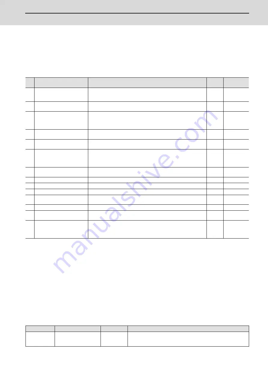
Dual signal warning (A4)
No.
Name
Details
Reset
method
Stop
method
96 Scale feedback error
An excessive difference in feedback amount was detected between the
main side encoder and the MPI scale in MPI scale absolute position detec-
tion system.
*
-
97 Scale offset error
An error was detected in the offset data that is read at the NC power-ON in
MPI scale absolute position detection system.
PR
-
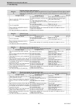
9B Incremental encoder/
magnetic pole shift warning
The difference between the magnetic pole position after the phase Z has
been passed (magnetic pole shift amount:SV028) and the initially detected
position is excessive in the built-in motor's incremental control system.The
magnetic pole is controlled by the initial detection value.
PR
-
9E Absolute position encoder:
Revolution counter error
An error was detected in the revolution counter data of the absolute posi-
tion encoder. The accuracy of absolute position is not guaranteed.
*
-
9F Battery voltage drop
The battery voltage to be supplied to the absolute position encoder is drop-
ping.
NR
-
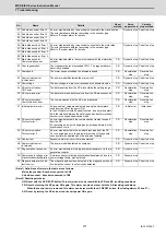
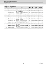
A3 In initial setup of ABS position
This warning is detected until the axis reaches the reference position during
the initial setup of the distance-coded reference check function. This warn-
ing turns OFF after the axis has reached the position, thus set the value dis-
played on the drive monitor to the parameter.
PR
-
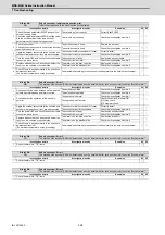
A4 Dual signal warning
An input was detected in the signal related to the dual signal.
Refer to "Dual signal warning (A4)" for details.
*
-
A6 Fan stop warning
A cooling fan in the drive unit stopped.
*
-
E0 Overregeneration warning
Over-regeneration detection level exceeded 80%.
*
-
E1 Overload warning
A level of 80% of the Overload 1 alarm state was detected.
*
-
E4 Parameter warning
An incorrect set value was detected among the parameters send from the
NC in the normal operation.
*
-
E6 Control axis detachment warning A control axis is being detached. (State display)
*
-
E7 NC emergency stop
In NC emergency stop. (State display)
*
Dec stop en-
abled
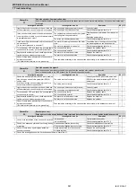
E8
to
EF
Power supply warning
The power supply unit detected a warning.
The error details are different according to the connected power supply unit.
Refer to "Power supply warning".
*
-
*EA:
Dec stop en-
abled
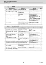
No.
Name
Sub info
Details
00A4.00
Dual signal warning
Axis name
The system has been set in the STO state. The STO state is also entered at
the time of emergency stop, but in this case, this warning will not appear be-
cause the emergency stop has priority.
Summary of Contents for MDS-E
Page 1: ......
Page 3: ......
Page 15: ......
Page 17: ......
Page 19: ......
Page 21: ......
Page 31: ......
Page 32: ...1 IB 1501229 F 1 Installation ...
Page 76: ...45 IB 1501229 F 2 Wiring and Connection ...
Page 132: ...101 IB 1501229 F 3 Safety Function ...
Page 142: ...111 IB 1501229 F 4 Setup ...
Page 277: ...MDS E EH Series Instruction Manual 4 Setup 246 IB 1501229 F ...
Page 278: ...247 IB 1501229 F 5 Servo Adjustment ...
Page 351: ...MDS E EH Series Instruction Manual 5 Servo Adjustment 320 IB 1501229 F ...
Page 352: ...321 IB 1501229 F 6 Spindle Adjustment ...
Page 404: ...373 IB 1501229 F 7 Troubleshooting ...
Page 455: ...MDS E EH Series Instruction Manual 7 Troubleshooting 424 IB 1501229 F ...
Page 456: ...425 IB 1501229 F 8 Maintenance ...
Page 475: ...MDS E EH Series Instruction Manual 8 Maintenance 444 IB 1501229 F ...
Page 476: ...445 IB 1501229 F 9 Power Backup System ...
Page 494: ...463 IB 1501229 F 10 Appx 1 Cable and Connector Assembly ...
Page 504: ...473 IB 1501229 F 11 Appx 2 D A Output Specifications for Drive Unit ...
Page 514: ...483 IB 1501229 F 12 Appx 3 Protection Function ...
Page 523: ...MDS E EH Series Instruction Manual 12 Appx 3 Protection Function 492 IB 1501229 F ...
Page 524: ...493 IB 1501229 F 13 Appx 4 Compliance to EC Directives ...
Page 528: ...497 IB 1501229 F 14 Appx 5 EMC Installation Guidelines ...
Page 540: ...509 IB 1501229 F 15 Appx 6 Higher Harmonic Suppression Measure Guidelines ...
Page 550: ......
Page 554: ......


