
MDS-E/EH Series Instruction Manual
7 Troubleshooting
387
IB-1501229-F
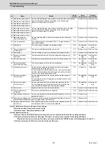
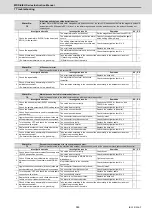
7.3 Troubleshooting
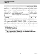
Follow this section to troubleshoot the alarms that occur during start up or while the machine is operating. If the state is
not improved with the following investigations, the drive unit may be faulty. Exchange the unit with another unit of the
same capacity, and check whether the state is improved.
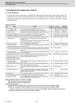
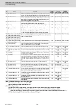
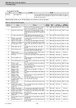
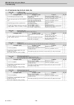
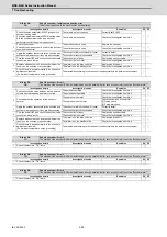
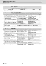
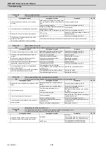
7.3.1 Troubleshooting at Power ON
If the NC system does not start up correctly and a system error occurs when the NC power is turned ON, the drive unit
may not have been started up properly. Check the LED display on the drive unit, and take measures according to this
section.
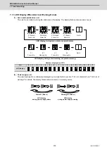
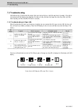
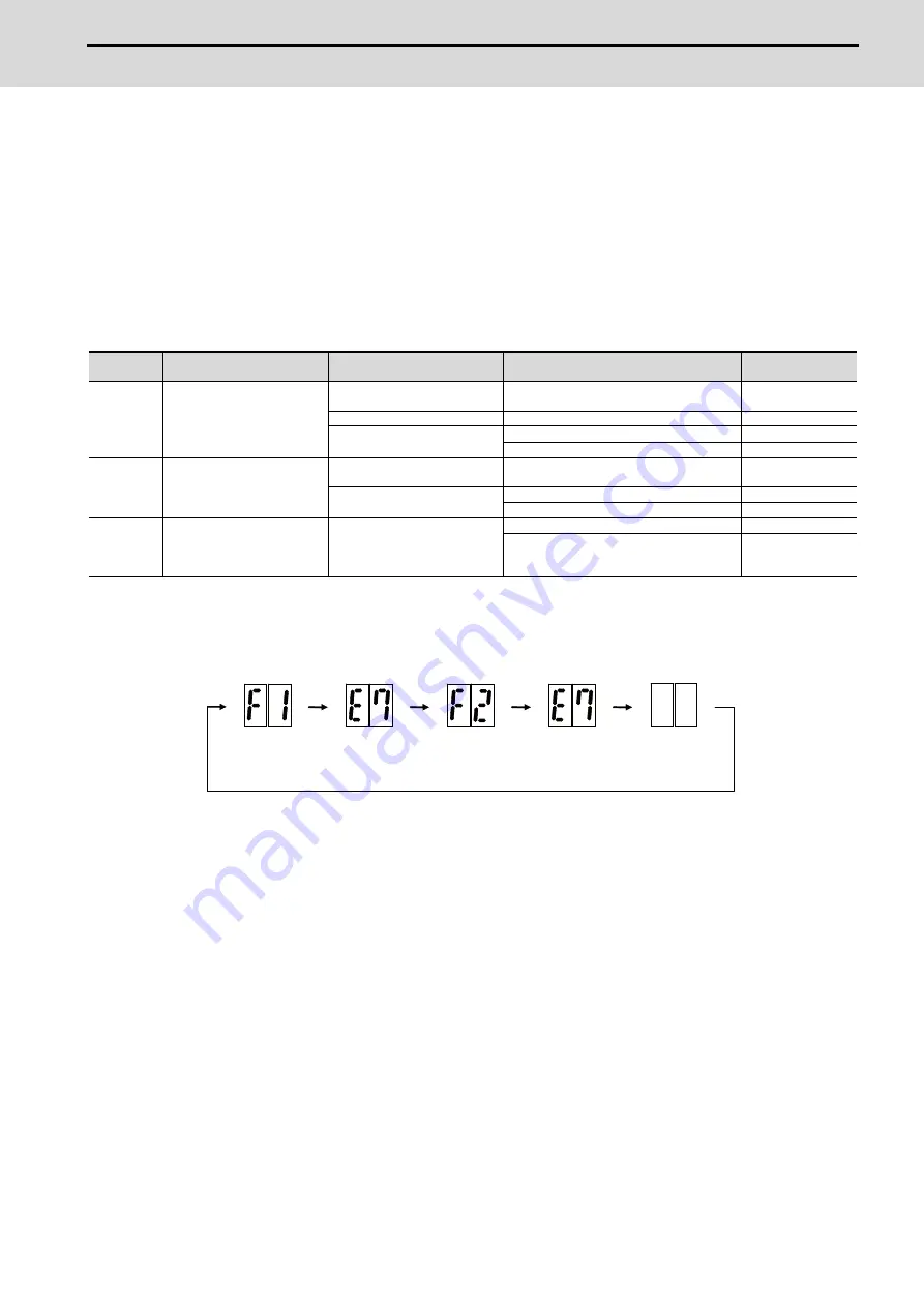
The drive unit has started up normally if the following type of emergency stop (E7) is displayed on the display unit's LED
display.
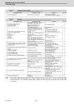
LED
display
Symptom
Cause of occurrence
Investigation method
Remedy
AA
Initial communication with the
CNC was not completed
correctly.
The drive unit axis No. setting is
incorrect.
Is there any other drive unit that has the same
axis No. set?
Set correctly.
The CNC setting is incorrect.
Is the No. of CNC controlled axes correct?
Set correctly.
Communication with CNC is
incorrect.
Is the connector (CN1A, CN1B) connected?
Connect correctly.
Is the cable broken?
Replace the cable.
Ab
Initial communication with the
CNC was not carried out.
The axis is not used, the setting is
for use inhibiting.
Is the DIP switch set correctly?
Set correctly.
Communication with CNC is
incorrect.
Is the connector (CN1A, CN1B) connected?
Connect correctly.
Is the cable broken?
Replace the cable.
12
An error was detected in the
unit's memory and IC during the
self-diagnosis at power ON.
The CPU peripheral circuit is
abnormal.
Check the repeatability.
Replace the unit.
Check whether there is any abnormality with
the unit's surrounding environment, etc.
Improve the
surrounding
environment.
F1
F+axis No.
E7
Emergency stop
Not lit
F2
F+axis No.
E7
Emergency stop
Normal drive unit LED display at NC power ON (for 1st axis)
Summary of Contents for MDS-E
Page 1: ......
Page 3: ......
Page 15: ......
Page 17: ......
Page 19: ......
Page 21: ......
Page 31: ......
Page 32: ...1 IB 1501229 F 1 Installation ...
Page 76: ...45 IB 1501229 F 2 Wiring and Connection ...
Page 132: ...101 IB 1501229 F 3 Safety Function ...
Page 142: ...111 IB 1501229 F 4 Setup ...
Page 277: ...MDS E EH Series Instruction Manual 4 Setup 246 IB 1501229 F ...
Page 278: ...247 IB 1501229 F 5 Servo Adjustment ...
Page 351: ...MDS E EH Series Instruction Manual 5 Servo Adjustment 320 IB 1501229 F ...
Page 352: ...321 IB 1501229 F 6 Spindle Adjustment ...
Page 404: ...373 IB 1501229 F 7 Troubleshooting ...
Page 455: ...MDS E EH Series Instruction Manual 7 Troubleshooting 424 IB 1501229 F ...
Page 456: ...425 IB 1501229 F 8 Maintenance ...
Page 475: ...MDS E EH Series Instruction Manual 8 Maintenance 444 IB 1501229 F ...
Page 476: ...445 IB 1501229 F 9 Power Backup System ...
Page 494: ...463 IB 1501229 F 10 Appx 1 Cable and Connector Assembly ...
Page 504: ...473 IB 1501229 F 11 Appx 2 D A Output Specifications for Drive Unit ...
Page 514: ...483 IB 1501229 F 12 Appx 3 Protection Function ...
Page 523: ...MDS E EH Series Instruction Manual 12 Appx 3 Protection Function 492 IB 1501229 F ...
Page 524: ...493 IB 1501229 F 13 Appx 4 Compliance to EC Directives ...
Page 528: ...497 IB 1501229 F 14 Appx 5 EMC Installation Guidelines ...
Page 540: ...509 IB 1501229 F 15 Appx 6 Higher Harmonic Suppression Measure Guidelines ...
Page 550: ......
Page 554: ......


