MDS-E/EH Series Instruction Manual
7 Troubleshooting
395
IB-1501229-F
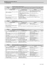
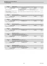
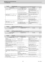
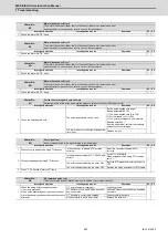
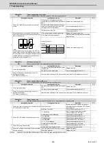
Alarm No.
31
Overspeed
The motor was detected to rotate at a speed exceeding the allowable speed (In the case of linear motor, it was detected to move
at a speed exceeding the allowable speed).
Investigation details
Investigation results
Remedies
SV SP
1
Check if the unit in which the alarm was detected is
servo or spindle.
The alarm was detected in servo.
Check the investigation item No. 2.
◯
◯
The alarm was detected in spindle.
Check the investigation item No. 3.
2
Check the servo parameters SV001 (PC1), SV002
(PC2), SV018 (PIT) and SV025 (MTYP) settings.
The settings are incorrect.
Correctly set.
◯
Correctly set.
Check the investigation item No. 5.
3
Check the spindle parameter SP026 (TSP) setting.
The setting is incorrect.
The alarm is detected at 115% of SP026.
Correctly set.
◯
Correctly set.
Check the investigation item No. 4.
4
Check the PLG output waveform.
There is a problem.
Adjust the PLG output waveform.
◯
◯
Normal.
Check the investigation item No. 5.
5
Check whether the speed waveform is
overshooting.
The waveform is overshooting.
Increase the acceleration/ deceleration time
constant.
Lower the load inertia.
◯
◯
The waveform is not overshooting.
Check if there is any abnormality in the unit's
ambient environment.
(Ex.: Ambient temperature, noise, grounding)
Check the investigation item No. 6.
6
Check the repeatability.
[1] The alarm occurs when the motor is
stopped.
[2] The rotation speed displayed on the drive
monitor varies when the motor is stopped.
Replace the encoder or encoder cable.
◯
◯
The alarm occurs at all time.
Replace the drive unit.
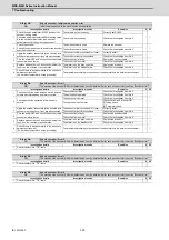
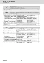
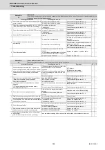
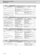
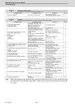
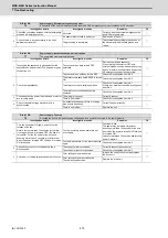
Alarm No.
32
Power module overcurrent
Overcurrent protection function in the power module has started its operation.
Investigation details
Investigation results
Remedies
SV SP
1
Disconnect the power cable (U, V, W) from the
unit’s terminal block and motor, and check whether
a short-circuit between the power cable or whether
conduction at both end of wiring occurs with a
tester.
[1] Before disconnecting the power cable, the
cable connector or screw has been
loosened.
[2] The short-circuit condition persists even
after disconnecting the cable from the unit
and motor.
[1] Tighten it.
[2] Check the motor wiring.
[3] Replace the power cable.
◯
◯
There is no problem.
Check the investigation item No. 2.
2
Check the motor insulation with a (megger) tester.
-Between motor power and ground earth
Less than 1M
Ω
. (Grounding)
Replace the motor.
◯
◯
1M
Ω
or more. (Normal)
Check the investigation item No. 3.
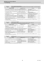
Check the unit capacity.
[1] The same size but smaller than the selected
capacity.
[2] The combination of the motor and axis is
alternated in a 2-axis unit.
The capacity is small.
The smaller capacity side was used in 2-axis
unit.
Replace to the unit of the selected capacity or
change the axis.
◯
◯
The motor meets the selected capacity.
Check the investigation item No. 3.
3
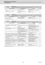
Check the current loop gain parameters.
Different from the standard parameter
settings.
Adjust the value to the standard setting.
◯
◯
Equivalent to the standard parameter
settings.
Check the investigation item No. 4.
4
Jiggle the encoder connectors (drive unit side and
encoder side) and check if they are disconnected.
The connector is disconnected (or loose).
Correctly install.
◯
◯
The connector is not disconnected.
Check the investigation item No. 5.
5
Turn the power OFF, and check the encoder cable
connection with a tester.
Connection is faulty.
Replace the encoder cable.
◯
◯
Connection is normal.
Check the investigation item No. 6.
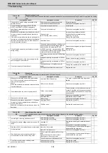
6
Check the repeatability.
The state returns to normal once, but occurs
sometimes thereafter.
Check the investigation item No. 8.
◯
◯
The error is always repeated.
Check the investigation item No. 7.
7
Replace with another unit, and check whether the
fault is on the drive unit side or encoder side.
The alarm is on the drive unit side.
Replace the drive unit.
◯
◯
The alarm is on the encoder side.
Replace the encoder.
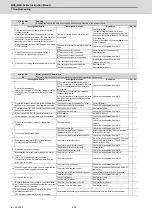
8
Check for any abnormalities in the unit's ambient
environment.
(Ex.: Ambient temperature, noise, grounding)
Take remedies according to the causes of the abnormality in the ambient environment.
◯
◯
Summary of Contents for MDS-E
Page 1: ......
Page 3: ......
Page 15: ......
Page 17: ......
Page 19: ......
Page 21: ......
Page 31: ......
Page 32: ...1 IB 1501229 F 1 Installation ...
Page 76: ...45 IB 1501229 F 2 Wiring and Connection ...
Page 132: ...101 IB 1501229 F 3 Safety Function ...
Page 142: ...111 IB 1501229 F 4 Setup ...
Page 277: ...MDS E EH Series Instruction Manual 4 Setup 246 IB 1501229 F ...
Page 278: ...247 IB 1501229 F 5 Servo Adjustment ...
Page 351: ...MDS E EH Series Instruction Manual 5 Servo Adjustment 320 IB 1501229 F ...
Page 352: ...321 IB 1501229 F 6 Spindle Adjustment ...
Page 404: ...373 IB 1501229 F 7 Troubleshooting ...
Page 455: ...MDS E EH Series Instruction Manual 7 Troubleshooting 424 IB 1501229 F ...
Page 456: ...425 IB 1501229 F 8 Maintenance ...
Page 475: ...MDS E EH Series Instruction Manual 8 Maintenance 444 IB 1501229 F ...
Page 476: ...445 IB 1501229 F 9 Power Backup System ...
Page 494: ...463 IB 1501229 F 10 Appx 1 Cable and Connector Assembly ...
Page 504: ...473 IB 1501229 F 11 Appx 2 D A Output Specifications for Drive Unit ...
Page 514: ...483 IB 1501229 F 12 Appx 3 Protection Function ...
Page 523: ...MDS E EH Series Instruction Manual 12 Appx 3 Protection Function 492 IB 1501229 F ...
Page 524: ...493 IB 1501229 F 13 Appx 4 Compliance to EC Directives ...
Page 528: ...497 IB 1501229 F 14 Appx 5 EMC Installation Guidelines ...
Page 540: ...509 IB 1501229 F 15 Appx 6 Higher Harmonic Suppression Measure Guidelines ...
Page 550: ......
Page 554: ......

