MDS-E/EH Series Instruction Manual
7 Troubleshooting
396
IB-1501229-F
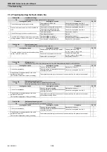
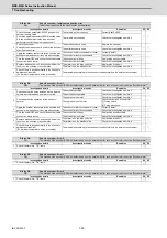
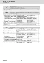
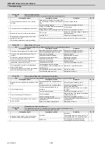
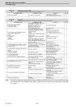
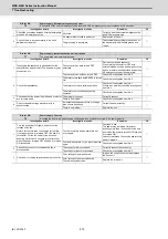
Alarm No.
33
Overvoltage:
The main circuit bus voltage exceeded the tolerable value.
Investigation details
Investigation results
Remedies
SV SP
1
Is an external regenerative resistor used?
An external regenerative resistor is used.
Check the investigation item No. 3.
◯
A built-in regenerative resistor is used.
Check the investigation item No. 2.
2
Is the short wire connected between P and D
terminal?
Are there any problems with the connection
condition?
The wire is not connected.
Connect the wire.
◯
The connector is disconnected.
The connector has a contact fault.
Reconnect the connector.
Replace the connector.
The connection is correct.
Check the investigation item No.6.
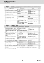
3
Is the combination of the used regenerative resistor
and drive unit appropriate?
The combination is incorrect.
Replace the correct regenerative resistor.
◯
◯
The combination is normal.
Check the investigation item No. 4.
4
Is the connection of the regenerative resistor or
regeneration resistor cable correct?
The connection is incorrect.
Rewire.
◯
◯
The connection is correct.
Check the investigation item No. 5.
5
Is the regeneration resistor or the regeneration
resistor cable broken?
Disconnect the regenerative resistor terminal and
check the resistance value with a tester.
The regeneration resistor is broken.
Or the resistance value is large.
Replace the regenerative resistor.
◯
◯
The regeneration resistor cable is broken.
Replace the cable.
The resistance value is normal.
Check the investigation item No. 6.
6
The acceleration/deceleration time constant is too
short.
At acceleration/deceleration, has the speed
overshoot reached to the current limit?
Reached to the current limit.
The speed overshoot is applied.
Increase the acceleration/deceleration time
constant.
◯
◯
The connection is normal.
Replace the drive unit.
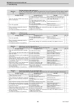
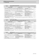
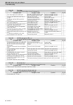
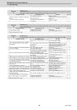
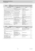
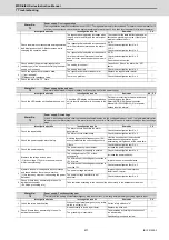
Alarm No.
34
NC-DRV communication: CRC error
An error was detected in the data received from the CNC.
Investigation details
Investigation results
Remedies
SV SP
1
Gently shake the connectors of the optical cables
by hand that link between NC and drive unit or
between drive units to check for loosening and
disconnection.
Also check if an excessive force is not applied on
them.
The connector is loose or nearly
disconnected. The tab of the connector is
damaged.
Correctly install.
Replace the cable.
◯
◯
The connector is not disconnected.
Check the investigation item No. 2.
2
Check for damages at the ends of the optical
communication cable.
Replace the cable.
The damage is found at the end of the cable. Replace the communication cable.
◯
◯
The connection is normal.
Check the investigation item No. 3.
3
Check whether the NC or drive unit software
version was changed recently.
The version was changed.
Change software version back to the original.
◯
◯
The version was not changed.
Check the investigation item No. 4.
4
Replace with another drive unit, and check whether
the fault is on the NC side or drive unit side.
The alarm is on the drive unit side.
Replace the drive unit.
◯
◯
The alarm is on the unit connections.
Check the investigation item No. 5.
5
Check if there is any abnormality in the unit's
ambient environment.
(Ex. Ambient temperature, noise, grounding)
Take remedies according to the causes of the abnormality in the ambient environment.
◯
◯
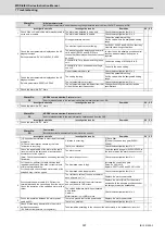
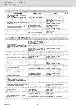
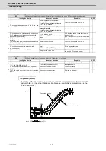
Alarm No.
35
NC command error
The travel command data that was received from the CNC was excessive.
Investigation details
Investigation results
Remedies
SV SP
1
Please contact the Service Center, Service Station, Sales Office or dealer.
◯
◯
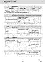
Alarm No.
36
NC-DRV communication: Communication error
The communication with the CNC was interrupted.
Investigation details
Investigation results
Remedies
SV SP
1
Check the alarm No. "34" items.
◯
◯
Summary of Contents for MDS-E
Page 1: ......
Page 3: ......
Page 15: ......
Page 17: ......
Page 19: ......
Page 21: ......
Page 31: ......
Page 32: ...1 IB 1501229 F 1 Installation ...
Page 76: ...45 IB 1501229 F 2 Wiring and Connection ...
Page 132: ...101 IB 1501229 F 3 Safety Function ...
Page 142: ...111 IB 1501229 F 4 Setup ...
Page 277: ...MDS E EH Series Instruction Manual 4 Setup 246 IB 1501229 F ...
Page 278: ...247 IB 1501229 F 5 Servo Adjustment ...
Page 351: ...MDS E EH Series Instruction Manual 5 Servo Adjustment 320 IB 1501229 F ...
Page 352: ...321 IB 1501229 F 6 Spindle Adjustment ...
Page 404: ...373 IB 1501229 F 7 Troubleshooting ...
Page 455: ...MDS E EH Series Instruction Manual 7 Troubleshooting 424 IB 1501229 F ...
Page 456: ...425 IB 1501229 F 8 Maintenance ...
Page 475: ...MDS E EH Series Instruction Manual 8 Maintenance 444 IB 1501229 F ...
Page 476: ...445 IB 1501229 F 9 Power Backup System ...
Page 494: ...463 IB 1501229 F 10 Appx 1 Cable and Connector Assembly ...
Page 504: ...473 IB 1501229 F 11 Appx 2 D A Output Specifications for Drive Unit ...
Page 514: ...483 IB 1501229 F 12 Appx 3 Protection Function ...
Page 523: ...MDS E EH Series Instruction Manual 12 Appx 3 Protection Function 492 IB 1501229 F ...
Page 524: ...493 IB 1501229 F 13 Appx 4 Compliance to EC Directives ...
Page 528: ...497 IB 1501229 F 14 Appx 5 EMC Installation Guidelines ...
Page 540: ...509 IB 1501229 F 15 Appx 6 Higher Harmonic Suppression Measure Guidelines ...
Page 550: ......
Page 554: ......

