MDS-E/EH Series Instruction Manual
7 Troubleshooting
401
IB-1501229-F
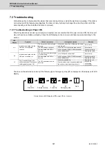
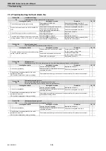
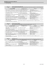
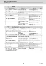
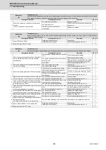
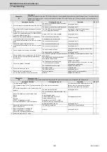
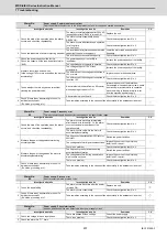
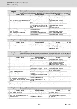
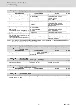
Alarm No.
48
Motor side encoder: Error 5
The motor side encoder (linear scale in the case of linear motor) detected an error.
As details differ for each encoder, refer to section "Encoder alarm".
Investigation details
Investigation results
Remedies
SV SP
1
Check the alarm No. "1B" items.
◯
◯
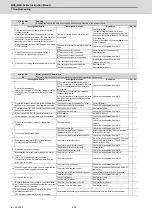
Alarm No.
49
Motor side encoder: Error 6
The motor side encoder (linear scale in the case of linear motor) detected an error.
As details differ for each encoder, refer to section "Encoder alarm".
Investigation details
Investigation results
Remedies
SV SP
1
Check the alarm No. "1B" items.
◯
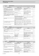
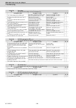
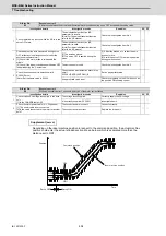
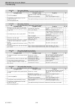
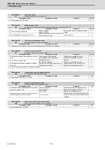
Alarm No.
4A
Motor side encoder: Error 7
The motor side encoder (linear scale in the case of linear motor) detected an error.
As details differ for each encoder, refer to section "Encoder alarm".
Investigation details
Investigation results
Remedies
SV SP
1
Check the alarm No. "1B" items.
◯
◯
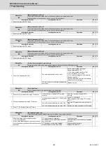
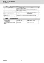
Alarm No.
4B
Motor side encoder: Error 8
The motor side encoder (linear scale in the case of linear motor) detected an error.
As details differ for each encoder, refer to section "Encoder alarm".
Investigation details
Investigation results
Remedies
SV SP
1
Check the alarm No. "1B" items.
◯
◯
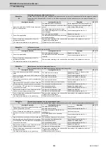
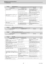
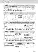
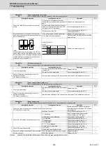
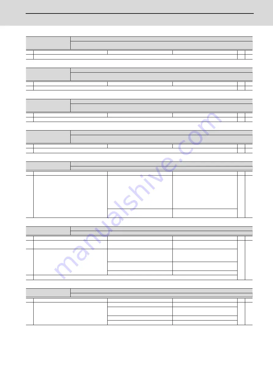
Alarm No.
4C
Current error at magnetic pole estimate
Current detection failed at the pulse-applied magnetic pole estimation by IPM spindle motor.
Investigation details
Investigation results
Remedies
SV SP
1
Check the pulse-applied time.
The pulse-applied time can be short.
Set the pulse-applied time longer.
Setting parameter:SP142
1) The pulse-applied time (0 to 350)
2) For low-speed coil:1)+1000
3) The polarity of magnetic pole estimate:
Reverse polarity is "-"
After the adjustment, perform the magnetic
pole detection control again.
-
◯
The alarm also occurs after the pulse-applied
time is set.
Replace the unit.
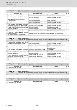
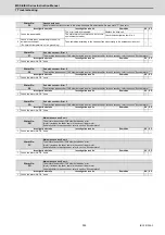
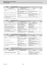
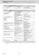
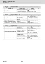
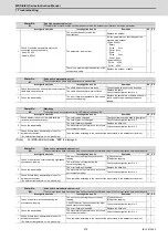
Alarm No.
4D
Dual signal error
An error was detected in the signal related to the dual signal.
Investigation details
Investigation results
Remedies
SV SP
1
When not using dedicated wiring STO function
Is the connector to disable STO installed
correctly?
Install the connector to disable STO
correctly.
◯
◯
2
When using dedicated wiring STO function
Is the parameter setting (SV113,SP229/bit8)
correct?
Set SV113,SP229/bit8.
When using dedicated wiring STO function,
set to "1 ".
The error is detected during the servo ON.
Input the STO signal after turning the servo
OFF.
The error is detected during the servo OFF. Remedy the wiring and signal for STO cable.
3
Check "7.3.6 Details of Alarm 4D" items.
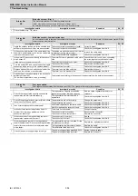
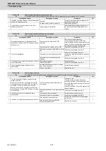
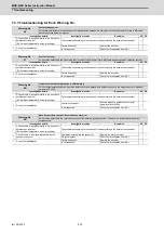
Alarm No.
4E
NC command mode error
The mode outside the specification was input in spindle control mode selection.
Investigation details
Investigation results
Remedies
SV SP
1
Check the wiring and setting environment.
1) Correctly grounded?
2) Any noise generating devices around the unit?
3) Are the speed/position encoder cables correctly
shielded?
1) The grounding is incomplete.
Correctly ground.
-
◯
2) The alarm occurs easily when a specific
device operates.
Use noise measures on the device described
on the left.
3) The cable is not correctly shielded.
Correctly shield the cable.
No abnormality is found in particular.
Replace the drive unit.
Summary of Contents for MDS-E
Page 1: ......
Page 3: ......
Page 15: ......
Page 17: ......
Page 19: ......
Page 21: ......
Page 31: ......
Page 32: ...1 IB 1501229 F 1 Installation ...
Page 76: ...45 IB 1501229 F 2 Wiring and Connection ...
Page 132: ...101 IB 1501229 F 3 Safety Function ...
Page 142: ...111 IB 1501229 F 4 Setup ...
Page 277: ...MDS E EH Series Instruction Manual 4 Setup 246 IB 1501229 F ...
Page 278: ...247 IB 1501229 F 5 Servo Adjustment ...
Page 351: ...MDS E EH Series Instruction Manual 5 Servo Adjustment 320 IB 1501229 F ...
Page 352: ...321 IB 1501229 F 6 Spindle Adjustment ...
Page 404: ...373 IB 1501229 F 7 Troubleshooting ...
Page 455: ...MDS E EH Series Instruction Manual 7 Troubleshooting 424 IB 1501229 F ...
Page 456: ...425 IB 1501229 F 8 Maintenance ...
Page 475: ...MDS E EH Series Instruction Manual 8 Maintenance 444 IB 1501229 F ...
Page 476: ...445 IB 1501229 F 9 Power Backup System ...
Page 494: ...463 IB 1501229 F 10 Appx 1 Cable and Connector Assembly ...
Page 504: ...473 IB 1501229 F 11 Appx 2 D A Output Specifications for Drive Unit ...
Page 514: ...483 IB 1501229 F 12 Appx 3 Protection Function ...
Page 523: ...MDS E EH Series Instruction Manual 12 Appx 3 Protection Function 492 IB 1501229 F ...
Page 524: ...493 IB 1501229 F 13 Appx 4 Compliance to EC Directives ...
Page 528: ...497 IB 1501229 F 14 Appx 5 EMC Installation Guidelines ...
Page 540: ...509 IB 1501229 F 15 Appx 6 Higher Harmonic Suppression Measure Guidelines ...
Page 550: ......
Page 554: ......


