
MDS-E/EH Series Instruction Manual
7 Troubleshooting
402
IB-1501229-F
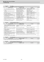
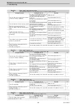
(Note)
NR and PR resetting are not possible when the overload level is 50% or more. Do not forcibly reset (AR) by turning
the unit power OFF. If AR resetting is used at 50% or higher, the level is set to 80% when the power is turned ON
next. (Servo)
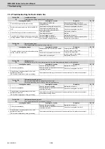
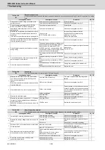
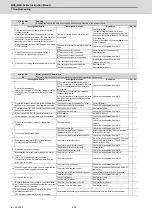
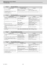
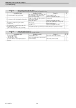
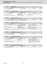
Alarm No.
4F
Instantaneous power interrupt
The control power supply has been shut down for 50ms or more.
Investigation details
Investigation results
Remedies
SV SP
1
Check the repeatability.
The alarm occurs occasionally.
Check the power facilities.
-
◯
Check the wiring of the control power.
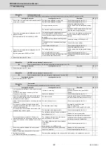
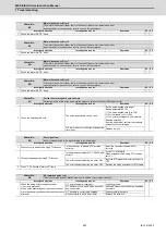
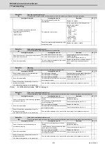
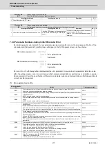
Alarm No.
50
Overload 1
Overload detection level became over 100%. The motor or the drive unit is overloaded.
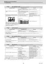
Investigation details
Investigation results
Remedies
SV SP
1
Check the overload parameters.
Servo:SV021, SV022
Spindle:SP021,SP022
The standard values (below) are not set.
Servo:SV021 = 60, SV022 = 150
Spindle:SP021=60,SP022=120
IPM:SP021=300,SP022=100
Set the standard values.
◯
◯
The standard values are set.
Investigate item 2.
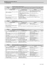
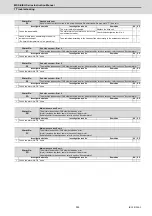
2
Check the items below displayed on the drive
monitor screen during operation.
<Servo>
Max.current 3 (%)
Overload(%)
<Spindle>
Load meter(%)
Perform the machining such as rapid
traverse, where an alarm occurs. The
examples are below.
<Servo>
[1] Max.current 3 constantly displays the
maximum value.
[2] Overload increases at a rapid speed.
<Spindle>
[1] The time to display 120% lasts long.
[2] The value is higher than normal.
Servo
[1] Mount a smaller workpiece.
[2] Increase the time constant.
[3] Check the investigation item No.6.
◯
◯
Spindle
[1] Lower the cutting amount.
[2] Extend the cycle time.
The value is within the supposed level and
there is no problem.
Investigate item 3.
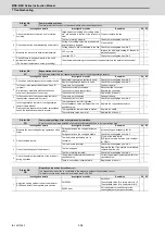
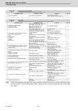
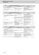
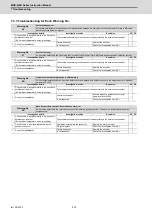
3
Check whether machine resonance is occurring.
Check for vibration and abnormal noise at the
spindle and table.
Resonance is occurring when a tool or
workpiece is mounted or during machining.
(The load inertia changes)
Adjust the parameters.
[1] Set the optimal notch filter.
[2] Lower VGN1 (SV005,SP005).
◯
◯
Resonance is not occurring.
Investigate item 4.
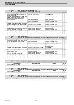
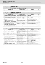
4
Check whether the shaft sways when the motor is
stopped.
"Hunting" of the spindle
"Vibration" of the table
The motor is hunting.
Adjust the parameters.
[1] Increase VGN1 (SV005, SP005).
[2] Lower VIA (SV008, SP008).
◯
◯
The motor is not hunting.
Servo: Investigate item 5
Spindle: Investigate item 7
5
Check the brake operation.
[1] Check the brake relay.
[2] Check the connector (CN20) connection.
The motor brakes are not released.
Correct the faulty section.
◯
The motor brake operation is normal.
Investigate item 6.
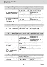
6
Check the load current with the NC Servo Monitor,
and investigate the machine load.
The cutting load is large.
Lower the cutting load.
◯
There is interference with the positioning pin.
When using the positioning pin, turn the
servo OFF when stopped.
An excessive force is applied from the
machine.
Check whether the ball screw is bent, or
whether there is a fault in the guide.
The machine load is not large.
Investigate item 8.
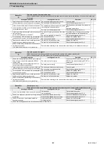
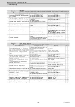
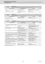
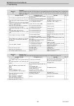
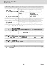
7
Check the PLG output waveform.
TS5690 cannot be checked.
There is a problem.
Adjust the PLG output waveform.
For TS5690, reinstall.
◯
Normal
Investigate item 8.
8
Confirm the motor capacity selection again.
The motor performance is insufficient.
Lower the acceleration/deceleration rate or
cutting load.
◯
◯
The motor performance is sufficient.
Check the tool mounted on the spindle.
- The service life is reached.
Increase the number of teeth (chips) of the
milling cutter, etc.
Investigate item 9.
9
Try replacing the drive unit.
Improved.
Use as it is.
◯
◯
Not improved.
Replace the motor.
Summary of Contents for MDS-E
Page 1: ......
Page 3: ......
Page 15: ......
Page 17: ......
Page 19: ......
Page 21: ......
Page 31: ......
Page 32: ...1 IB 1501229 F 1 Installation ...
Page 76: ...45 IB 1501229 F 2 Wiring and Connection ...
Page 132: ...101 IB 1501229 F 3 Safety Function ...
Page 142: ...111 IB 1501229 F 4 Setup ...
Page 277: ...MDS E EH Series Instruction Manual 4 Setup 246 IB 1501229 F ...
Page 278: ...247 IB 1501229 F 5 Servo Adjustment ...
Page 351: ...MDS E EH Series Instruction Manual 5 Servo Adjustment 320 IB 1501229 F ...
Page 352: ...321 IB 1501229 F 6 Spindle Adjustment ...
Page 404: ...373 IB 1501229 F 7 Troubleshooting ...
Page 455: ...MDS E EH Series Instruction Manual 7 Troubleshooting 424 IB 1501229 F ...
Page 456: ...425 IB 1501229 F 8 Maintenance ...
Page 475: ...MDS E EH Series Instruction Manual 8 Maintenance 444 IB 1501229 F ...
Page 476: ...445 IB 1501229 F 9 Power Backup System ...
Page 494: ...463 IB 1501229 F 10 Appx 1 Cable and Connector Assembly ...
Page 504: ...473 IB 1501229 F 11 Appx 2 D A Output Specifications for Drive Unit ...
Page 514: ...483 IB 1501229 F 12 Appx 3 Protection Function ...
Page 523: ...MDS E EH Series Instruction Manual 12 Appx 3 Protection Function 492 IB 1501229 F ...
Page 524: ...493 IB 1501229 F 13 Appx 4 Compliance to EC Directives ...
Page 528: ...497 IB 1501229 F 14 Appx 5 EMC Installation Guidelines ...
Page 540: ...509 IB 1501229 F 15 Appx 6 Higher Harmonic Suppression Measure Guidelines ...
Page 550: ......
Page 554: ......


