MDS-E/EH Series Instruction Manual
7 Troubleshooting
404
IB-1501229-F
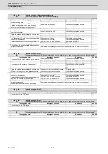
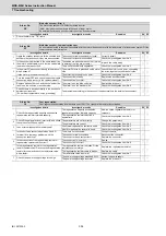
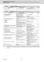
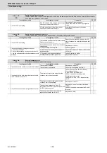
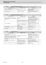
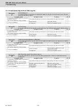
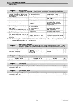
Alarm No.
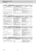
53
Excessive error 2
A difference between the actual and theoretical motor positions during servo OFF exceeded the setting value.
Investigation details
Investigation results
Remedies
SV SP
1
Check the follow-up function while the NC is in the
servo OFF state.
The axis detachment function (NC
parameter) is invalid.
(Note) For the axis detachment function,
refer to the NC manual.
Check the investigation item No. 2.
◯
The axis detachment function (NC
parameter) is valid.
(Note) For the axis detachment function,
refer to the NC manual.
Check the investigation item No. 3.
2
Check whether the axis has moved during servo
OFF (either by visual inspection or monitor the
position droop waveform).
[1] Check if the motor brake is released in the
middle.
[2] Check if the axis moves because the servo OFF
is applied during the C axis mode.
[1] The axis has moved.
[2] The servo OFF is applied during the
mode.
[1] Adjust the brakes, etc. so that the axis
does not move.
[2] Avoid the servo OFF from being applied
during position control.
◯
The axis has not moved.
Check the investigation item No. 3.
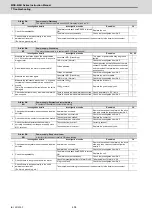
3
Check the excessive error detection width.
SV026 (Servo)
(Note) Set the same value to SV023.
The excessive error detection width is too
small.
SV026 ={RAPID/(60*PGN1)}/2
Set an appropriate value.
◯
An appropriate value is set.
Check for problems on the NC side, such as
the position FB follow-up control.
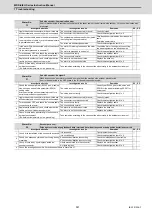
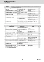
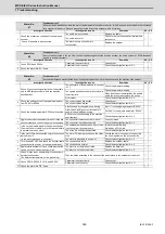
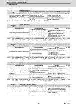
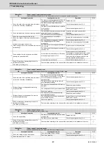
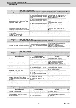
Alarm No.
54
Excessive error 3
When an excessive error 1 occurred, detection of the motor current failed.
Investigation details
Investigation results
Remedies
SV SP
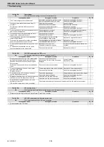
1
Check that the PN voltage is supplied to the drive
unit.
[1] Is the CHARGE lamp ON?
The voltage is not supplied.
Correctly supply the PN voltage.
◯
◯
It is correctly supplied (DC300V).
Investigate item 2.
2
Check the motor power cable (U, V, W phases).
[1] The power cable is not connected.
[2] Is the cable connected to the motor for another
axis?
The connections are incorrect.
Connect correctly.
◯
◯
The connections are correct.
Replace the drive unit.
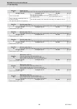
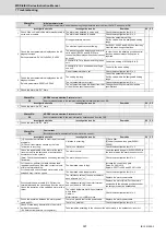
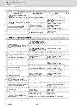
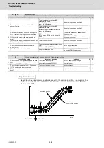
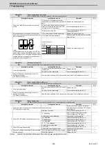
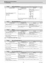
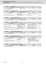
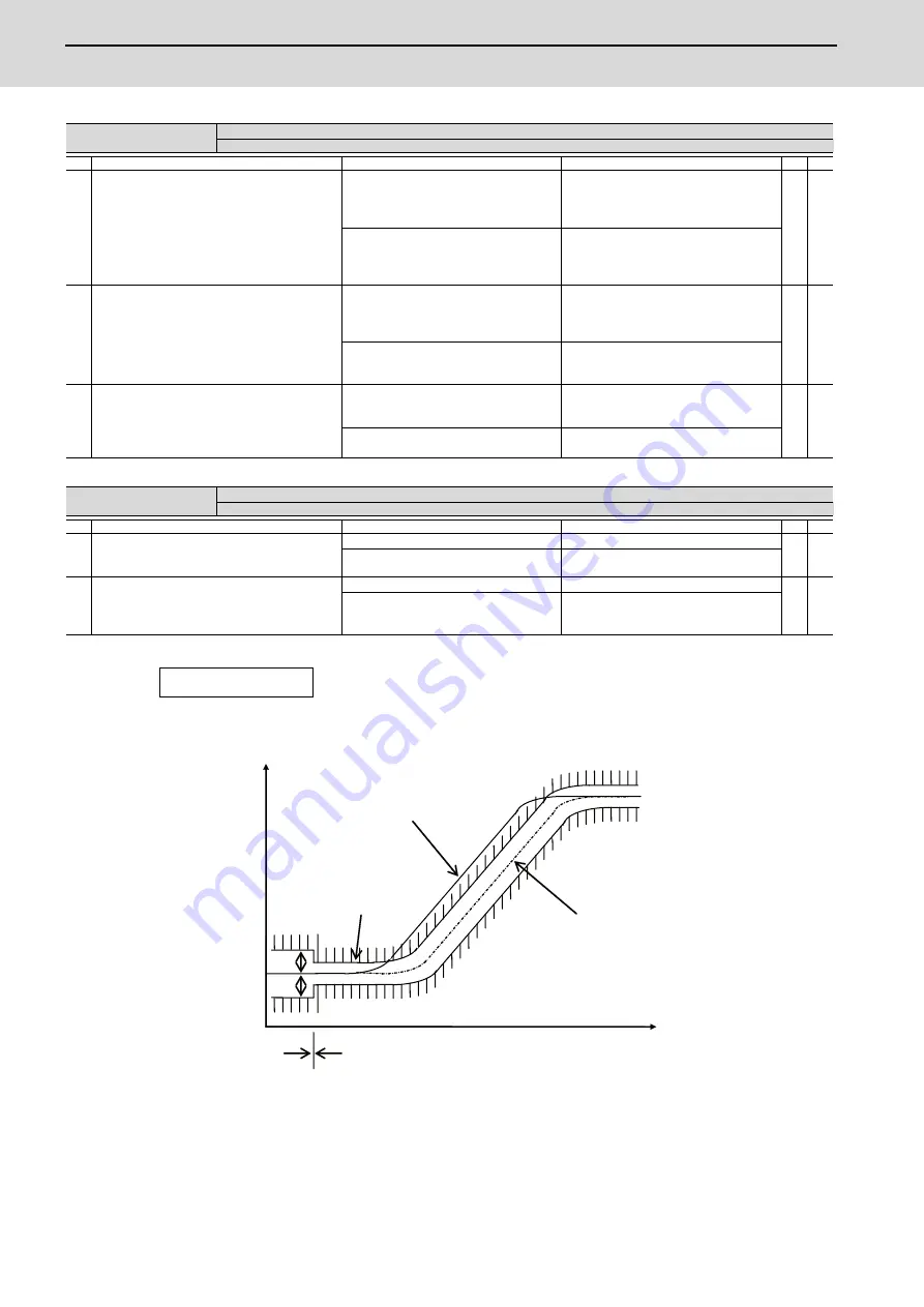
Servo OFF
Servo ON
Time
OD1
OD1
OD2
OD2
Position
Depending on the ideal machine position in respect to the command position, the actual machine
position could enter the actual shaded section shown below, which is separated more than the
distance set in OD1.
Supplement (servo)
Ideal machine position
Command position
Summary of Contents for MDS-E
Page 1: ......
Page 3: ......
Page 15: ......
Page 17: ......
Page 19: ......
Page 21: ......
Page 31: ......
Page 32: ...1 IB 1501229 F 1 Installation ...
Page 76: ...45 IB 1501229 F 2 Wiring and Connection ...
Page 132: ...101 IB 1501229 F 3 Safety Function ...
Page 142: ...111 IB 1501229 F 4 Setup ...
Page 277: ...MDS E EH Series Instruction Manual 4 Setup 246 IB 1501229 F ...
Page 278: ...247 IB 1501229 F 5 Servo Adjustment ...
Page 351: ...MDS E EH Series Instruction Manual 5 Servo Adjustment 320 IB 1501229 F ...
Page 352: ...321 IB 1501229 F 6 Spindle Adjustment ...
Page 404: ...373 IB 1501229 F 7 Troubleshooting ...
Page 455: ...MDS E EH Series Instruction Manual 7 Troubleshooting 424 IB 1501229 F ...
Page 456: ...425 IB 1501229 F 8 Maintenance ...
Page 475: ...MDS E EH Series Instruction Manual 8 Maintenance 444 IB 1501229 F ...
Page 476: ...445 IB 1501229 F 9 Power Backup System ...
Page 494: ...463 IB 1501229 F 10 Appx 1 Cable and Connector Assembly ...
Page 504: ...473 IB 1501229 F 11 Appx 2 D A Output Specifications for Drive Unit ...
Page 514: ...483 IB 1501229 F 12 Appx 3 Protection Function ...
Page 523: ...MDS E EH Series Instruction Manual 12 Appx 3 Protection Function 492 IB 1501229 F ...
Page 524: ...493 IB 1501229 F 13 Appx 4 Compliance to EC Directives ...
Page 528: ...497 IB 1501229 F 14 Appx 5 EMC Installation Guidelines ...
Page 540: ...509 IB 1501229 F 15 Appx 6 Higher Harmonic Suppression Measure Guidelines ...
Page 550: ......
Page 554: ......


