MDS-E/EH Series Instruction Manual
7 Troubleshooting
406
IB-1501229-F
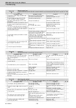
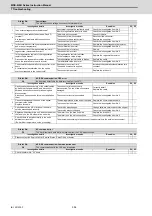
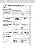
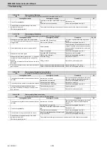
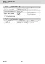
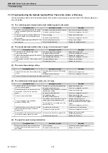
Alarm No.
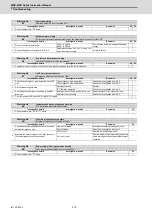
5D
Safely limited: Door state error
In safely limited mode, the door state signal from the NC and the same signal from the drive unit don't match. Otherwise, door
open state was detected in normal mode.
Investigation details
Investigation results
Remedies
SV SP
1
Check the DI input timing.
Both NC side and drive unit side input timings
match one another within 500ms.
Review the DI input sequence.
Check if the cable for the DI input signal is
broken.
◯
◯
NC side and drive unit side inputs do not
match one another within 500ms.
Investigate the wiring and connection
environment.
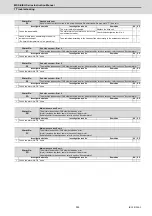
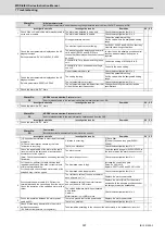
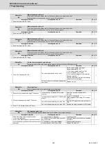
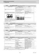
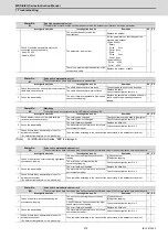
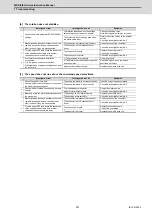
Alarm No.
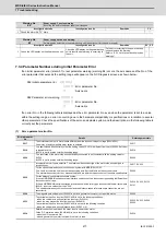
5E
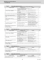
Safely limited: Feedback speed error
In safely limited mode, the motor speed was detected to exceed the safely limited speed.
Investigation details
Investigation results
Remedies
SV SP
1
Check the DI input timing.
The feedback speed and safely limited speed
limit value are the same.
Reduce the commanded speed on the NC
side or increase the safely limited speed limit
value.
◯
◯
The feedback speed is slower than the safely
limited speed.
Replace the drive unit.
2
Check the wiring and setting environment.
1) Correctly grounded?
2) Any noise generating devices around the unit?
3) Are the speed/position encoder cables correctly
shielded?
1) The grounding is incomplete.
Correctly ground.
◯
◯
2) The alarm occurs easily when a specific
device operates.
Use noise measures on the device described
on the left.
3) The cable is not correctly shielded.
Correctly shield the cable.
No abnormality is found in particular.
Replace the drive unit.
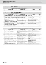
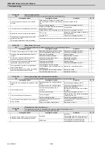
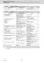
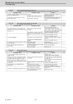
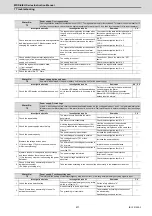
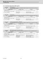
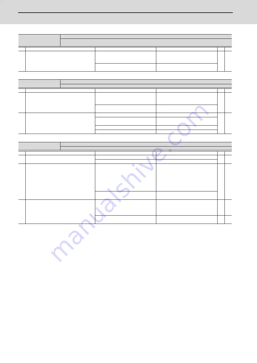
Alarm No.
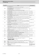
5F
External contactor error
A contact of the external contactor is welding.
Investigation details
Investigation results
Remedies
SV SP
1
Check whether the contactor's contact has melted.
The contactor is melted.
Replace the contactor.
◯
◯
The contactor is not melted.
Check the investigation item No. 2.
2
Check whether the axis where an alarm occurred
was a contactor control axis.
The alarm occurred at the axis where the
contactor control is not executed.
Check the parameter. (EJ/EJH Series)
With contactor control
Servo:SV082, Spindle:SP227
0800h is added to the setting value.
Without contactor control
Change "Bit A,B" to "00" in the parameter
above.
◯
◯
The alarm occurred at the axis where the
contactor control is executed.
Replace the drive unit.
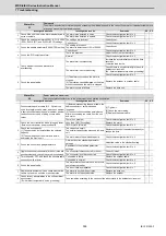
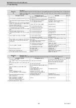
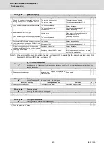
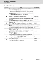
3
Check the connection with a regenerative resistor.
The short wire between the P and D
terminals of the control circuit terminal block
(CNP2) is disconnected.
Replace the control circuit terminal block
(CNP2).
Connect the short wire between the P and D
terminals.
◯
The connection with an external option
regenerative resistor unit is faulty.
Replace the cable.
◯
◯
Summary of Contents for MDS-E
Page 1: ......
Page 3: ......
Page 15: ......
Page 17: ......
Page 19: ......
Page 21: ......
Page 31: ......
Page 32: ...1 IB 1501229 F 1 Installation ...
Page 76: ...45 IB 1501229 F 2 Wiring and Connection ...
Page 132: ...101 IB 1501229 F 3 Safety Function ...
Page 142: ...111 IB 1501229 F 4 Setup ...
Page 277: ...MDS E EH Series Instruction Manual 4 Setup 246 IB 1501229 F ...
Page 278: ...247 IB 1501229 F 5 Servo Adjustment ...
Page 351: ...MDS E EH Series Instruction Manual 5 Servo Adjustment 320 IB 1501229 F ...
Page 352: ...321 IB 1501229 F 6 Spindle Adjustment ...
Page 404: ...373 IB 1501229 F 7 Troubleshooting ...
Page 455: ...MDS E EH Series Instruction Manual 7 Troubleshooting 424 IB 1501229 F ...
Page 456: ...425 IB 1501229 F 8 Maintenance ...
Page 475: ...MDS E EH Series Instruction Manual 8 Maintenance 444 IB 1501229 F ...
Page 476: ...445 IB 1501229 F 9 Power Backup System ...
Page 494: ...463 IB 1501229 F 10 Appx 1 Cable and Connector Assembly ...
Page 504: ...473 IB 1501229 F 11 Appx 2 D A Output Specifications for Drive Unit ...
Page 514: ...483 IB 1501229 F 12 Appx 3 Protection Function ...
Page 523: ...MDS E EH Series Instruction Manual 12 Appx 3 Protection Function 492 IB 1501229 F ...
Page 524: ...493 IB 1501229 F 13 Appx 4 Compliance to EC Directives ...
Page 528: ...497 IB 1501229 F 14 Appx 5 EMC Installation Guidelines ...
Page 540: ...509 IB 1501229 F 15 Appx 6 Higher Harmonic Suppression Measure Guidelines ...
Page 550: ......
Page 554: ......


