MDS-E/EH Series Instruction Manual
7 Troubleshooting
408
IB-1501229-F
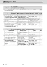
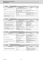
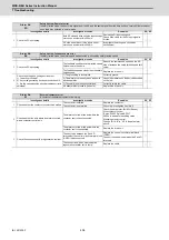
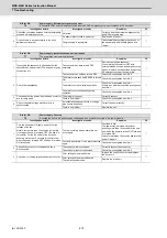
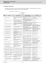
Alarm No.
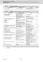
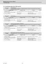
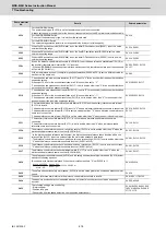
68
Power supply: Watchdog
The system does not operate correctly. LED display is fixed as "8".
Investigation details
Investigation results
Remedies
CV
1
Check the repeatability.
The alarm occurs each time READY is turned
ON.
Replace the unit.
◯
The alarm occurs occasionally.
Check the investigation item No. 2.
2
Check if there is any abnormality in the unit's
ambient environment.
(Ex. Noise, grounding, etc.)
Take remedies according to the causes of the abnormality in the ambient environment.
◯
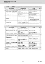
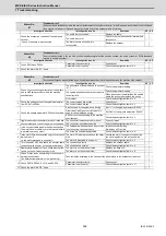
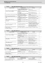
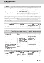
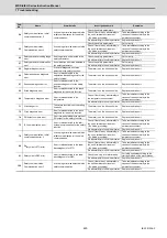
Alarm No.
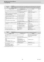
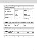
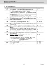
69
Power supply: Grounding
The motor power cable is in contact with FG (Frame Ground).
Investigation details
Investigation results
Remedies
SV SP
1
Measure the insulation across the power cables
(U,V,W) for all motors and the ground. (Carry out a
megger test.)
Less than 1M
Ω
. (Grounding)
The motor or power cable may be ground
faulted.
◯
◯
1M
Ω
or more. (Normal)
Check the investigation item No. 2.
2
Has oil adhered on the motor or power cable?
Oil has adhered.
Take measures so that oil does not come in
contact. Check the motor's cannon connector
and the inside of the terminal box, and clean
as necessary.
◯
◯
Oil has not adhered.
Check the investigation item No. 3.
3
Measure the insulation again.
Less than 1M
Ω
. (Grounding)
Replace the motor or cable.
◯
◯
1M
Ω
or more. (Normal)
Check the investigation item No. 2.
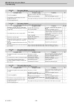
4
Measure the resistance across the U, V, W phase
terminals of the servo/spindle drive unit and the
ground.
(Note) Do not measure the insulation as the unit is
damaged.
Less than 100k .
Replace the drive unit.
◯
◯
100k or more.
Replace the power supply unit.
5
Check whether there is any axis in which alarm 24
has occurred.
There is an axis in which alarm has occurred. Check the alarm No. "24" items.
◯
◯
There is no axis in which alarm has occurred. Check the investigation item No. 2.
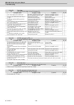
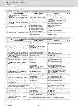
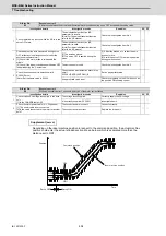
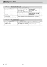
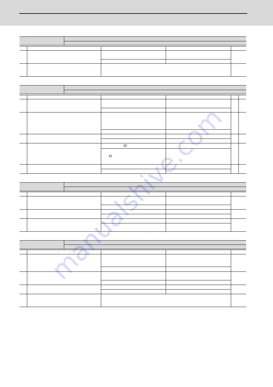
Alarm No.
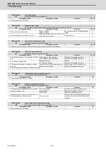
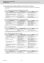
6A
Power supply: External contactor welding
A contact of the external contactor is welding.
Investigation details
Investigation results
Remedies
CV
1
Check whether any alarm has occurred on the drive
unit side.
An alarm has occurred.
Remove the cause of the alarm on the drive
side, and check the investigation item No. 2.
◯
An alarm has not occurred.
Check the investigation item No. 2.
2
Check whether the contactor's contact has melted.
The contactor has melted.
Replace the contactor.
◯
The contactor has not melted.
Check the investigation item No. 3.
3
Check that the contactor excitation wiring is
correctly connected from the power supply unit's
MC1 terminal.
The connection is correct.
Correctly connect.
◯
The connection is incorrect.
Replace the power supply unit.
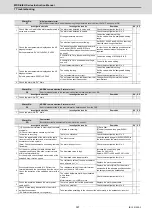
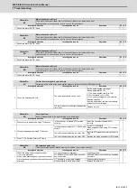
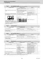
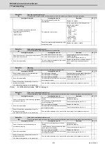
Alarm No.
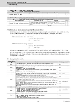
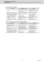
6B
Power supply: Rush circuit error
A thyristor for rush short circuit is ON when rushing.
Investigation details
Investigation results
Remedies
CV
1
Check whether any alarm has occurred on the drive
unit side.
An alarm has occurred.
Remove the cause of the alarm on the drive
side, and then carry out the investigation
details 2.
◯
An alarm has not occurred.
Check the investigation item No. 2.
2
Check the repeatability.
The alarm occurs each time READY is turned
ON.
Replace the unit.
◯
The alarm occurs occasionally.
Check the investigation item No. 3.
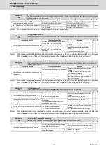
3
Check if there is any ground fault in the motor.
Check the investigation item of Alarm No. 69. Take remedies of Alarm No. 69.
◯
No ground fault.
Check the investigation item No. 4.
4
Check if there is any abnormality in the unit's
ambient environment.
(Ex. Noise, grounding, etc.)
Take remedies according to the causes of the abnormality in the ambient environment.
◯
Summary of Contents for MDS-E
Page 1: ......
Page 3: ......
Page 15: ......
Page 17: ......
Page 19: ......
Page 21: ......
Page 31: ......
Page 32: ...1 IB 1501229 F 1 Installation ...
Page 76: ...45 IB 1501229 F 2 Wiring and Connection ...
Page 132: ...101 IB 1501229 F 3 Safety Function ...
Page 142: ...111 IB 1501229 F 4 Setup ...
Page 277: ...MDS E EH Series Instruction Manual 4 Setup 246 IB 1501229 F ...
Page 278: ...247 IB 1501229 F 5 Servo Adjustment ...
Page 351: ...MDS E EH Series Instruction Manual 5 Servo Adjustment 320 IB 1501229 F ...
Page 352: ...321 IB 1501229 F 6 Spindle Adjustment ...
Page 404: ...373 IB 1501229 F 7 Troubleshooting ...
Page 455: ...MDS E EH Series Instruction Manual 7 Troubleshooting 424 IB 1501229 F ...
Page 456: ...425 IB 1501229 F 8 Maintenance ...
Page 475: ...MDS E EH Series Instruction Manual 8 Maintenance 444 IB 1501229 F ...
Page 476: ...445 IB 1501229 F 9 Power Backup System ...
Page 494: ...463 IB 1501229 F 10 Appx 1 Cable and Connector Assembly ...
Page 504: ...473 IB 1501229 F 11 Appx 2 D A Output Specifications for Drive Unit ...
Page 514: ...483 IB 1501229 F 12 Appx 3 Protection Function ...
Page 523: ...MDS E EH Series Instruction Manual 12 Appx 3 Protection Function 492 IB 1501229 F ...
Page 524: ...493 IB 1501229 F 13 Appx 4 Compliance to EC Directives ...
Page 528: ...497 IB 1501229 F 14 Appx 5 EMC Installation Guidelines ...
Page 540: ...509 IB 1501229 F 15 Appx 6 Higher Harmonic Suppression Measure Guidelines ...
Page 550: ......
Page 554: ......


