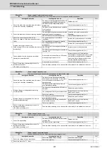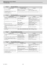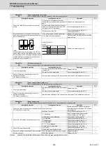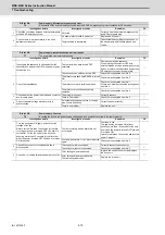
MDS-E/EH Series Instruction Manual
7 Troubleshooting
409
IB-1501229-F
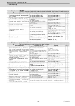
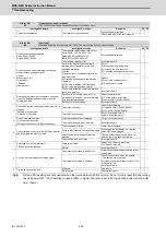
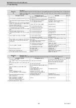
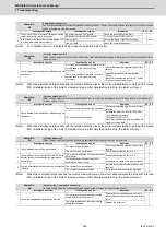
(Note)
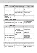
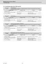
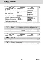
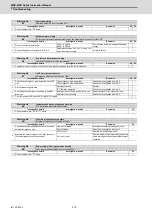
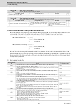
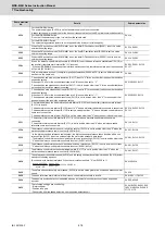
Alarm 6F is detected at the same time other power supply alarms occur.
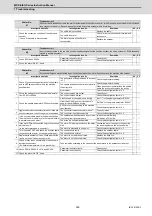
Alarm No.
6C
Power supply: Main circuit error
An error was detected in charging operation of the main circuit capacitor.
Investigation details
Investigation results
Remedies
CV
1
Check the CHARGE lamp state when the alarm
occurs.
[1] The light of the lamp becomes faint.
[2] An alarm occurs when ready is turned ON
again.
Replace the power supply unit.
◯
The lamp turns ON instantly, but when the
alarm occurs and the contactor turns OFF,
the lamp turns OFF immediately.
Check the investigation item No. 2.
The lamp never turns ON.
Check the investigation item No. 2.
Then replace the unit.
2
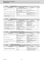
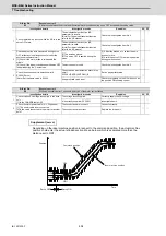
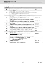
Disconnect the power supply unit's PN terminal
block wiring, and measure the resistance value at 1)
and 2) shown below.
(Note)
When disconnecting the PN wiring, turn OFF the
power, make sure the CHARGE lamp has turned
OFF at contactor OFF and then wait at least fifteen
minutes before disconnecting. Do not disconnect
immediately after the power OFF.
1)The power supply unit side is abnormal.
Replace the power supply unit.
◯
2)The drive unit side is abnormal.
Disconnect the PN wiring, and then check the
drive unit side.
1) and 2) are both
normal.
Replace the power supply unit.
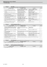
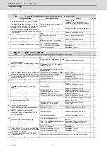
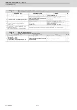
Alarm No.
6D
Parameter setting error
An error was detected in the parameter sent from the drive unit.
Investigation details
Investigation results
Remedies
CV
1
Check the repeatability.
The alarm occurs each time after the power
is turned ON.
Replace the unit.
◯
The alarm occurs occasionally.
Check the investigation item No. 2.
2
Check if there is any abnormality in the unit's
ambient environment.
(Ex. Noise, grounding, etc.)
Take remedies according to the causes of the abnormality in the ambient environment.
◯
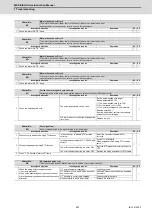
Alarm No.
6E
Power supply: H/W error/AD error
An error was detected in the internal memory or A/D converter.
Investigation details
Investigation results
Remedies
CV
1
Check the repeatability.
The alarm occurs each time READY is turned
ON.
Replace the unit.
◯
The alarm occurs occasionally.
Check the investigation item No. 2.
2
Check if there is any abnormality in the unit's
ambient environment.
(Ex. Noise, grounding, etc.)
Take remedies according to the causes of the abnormality in the ambient environment.
◯
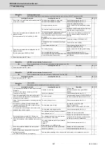
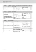
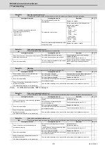
Alarm No.
6F
Power supply error
No power supply is connected to the drive unit, or a communication error was detected.
Investigation details
Investigation results
Remedies
CV
1
Check the time from when the unit power is turned
OFF till when it is turned ON.
Within 3 seconds
Assure more than 3 seconds for the time
from when the power is turned OFF till when
it is turned ON.
◯
More than 3 seconds
Check the investigation item No. 2.
2
Check the LED display on the power supply unit.
"F" is flickering.
An A/D converter error has occurred.
Check the alarm No. "6E" items.
◯
Another alarm code is flickering.
Check items of each alarm No.
"0" is displayed.
Check the investigation item No. 3.
"F" is displayed.
Check the investigation item No. 3.
"8" is displayed.
Check the alarm No. "68" items.
"b", "C", "d" is displayed.
Check the investigation item No. 4.
Something else is displayed.
Check the alarm No. "68" items.
3
Check the rotary switch setting.
0 or 4 is set.
Check the investigation item No. 4.
◯
A value other than the above is set.
Correctly set the rotary switch.
4
Check the communication cable (CN4) connected
with the drive unit.
There is a problem with the wiring or shield. Replace the cable.
◯
There is no problem.
Replace the unit.
Drive unit
Power supply
unit
P
N
2)
1)
Tester
measure-
ment point
Polarity
Normal
Abnormal
Several 100Ω
Several 100Ω
Short-circuit/∞Ω
Several 100Ω
Several 100Ω
Short-circuit/∞Ω
2)
1)
∞Ω
∞Ω
+
-
P
N
P
N
P
N
P
N
Summary of Contents for MDS-E
Page 1: ......
Page 3: ......
Page 15: ......
Page 17: ......
Page 19: ......
Page 21: ......
Page 31: ......
Page 32: ...1 IB 1501229 F 1 Installation ...
Page 76: ...45 IB 1501229 F 2 Wiring and Connection ...
Page 132: ...101 IB 1501229 F 3 Safety Function ...
Page 142: ...111 IB 1501229 F 4 Setup ...
Page 277: ...MDS E EH Series Instruction Manual 4 Setup 246 IB 1501229 F ...
Page 278: ...247 IB 1501229 F 5 Servo Adjustment ...
Page 351: ...MDS E EH Series Instruction Manual 5 Servo Adjustment 320 IB 1501229 F ...
Page 352: ...321 IB 1501229 F 6 Spindle Adjustment ...
Page 404: ...373 IB 1501229 F 7 Troubleshooting ...
Page 455: ...MDS E EH Series Instruction Manual 7 Troubleshooting 424 IB 1501229 F ...
Page 456: ...425 IB 1501229 F 8 Maintenance ...
Page 475: ...MDS E EH Series Instruction Manual 8 Maintenance 444 IB 1501229 F ...
Page 476: ...445 IB 1501229 F 9 Power Backup System ...
Page 494: ...463 IB 1501229 F 10 Appx 1 Cable and Connector Assembly ...
Page 504: ...473 IB 1501229 F 11 Appx 2 D A Output Specifications for Drive Unit ...
Page 514: ...483 IB 1501229 F 12 Appx 3 Protection Function ...
Page 523: ...MDS E EH Series Instruction Manual 12 Appx 3 Protection Function 492 IB 1501229 F ...
Page 524: ...493 IB 1501229 F 13 Appx 4 Compliance to EC Directives ...
Page 528: ...497 IB 1501229 F 14 Appx 5 EMC Installation Guidelines ...
Page 540: ...509 IB 1501229 F 15 Appx 6 Higher Harmonic Suppression Measure Guidelines ...
Page 550: ......
Page 554: ......

