MDS-E/EH Series Instruction Manual
7 Troubleshooting
415
IB-1501229-F
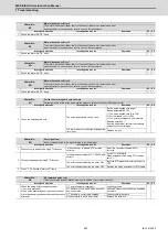
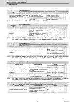
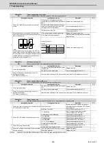
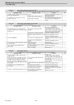
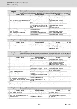
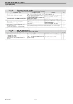
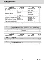
(Note 1) When warning 9F occurs, do not turn the drive unit power OFF to ensure that the absolute position data is held.
Replace the battery with the drive unit power ON.
Warning No.
9F
Battery voltage drop
The battery voltage that is supplied to the absolute position encoder dropped. The absolute position data is retained.
Investigation details
Investigation results
Remedies
SV SP
1
Change the used battery and check whether the
warning does not occur. (Turning the power OFF
and ON is required.)
The warning does not occur.
The battery has been drained.
◯
The warning occurs.
Check the investigation item No. 2.
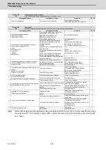
2
Check whether the battery cable is disconnected,
broken, or wired incorrectly.
The connection is faulty.
Correct the connection.
Replace the cable.
◯
The connection is normal.
Check the investigation item No. 3.
3
Measure the new battery voltage.
Less than 3.4V.
Replace the battery.
◯
3.4V or more.
Check the investigation item No. 6.
When a battery box is used, check the
investigation item No. 4.
4
Check whether the cable connecting between the
battery box and CN9 is short-circuited, broken, or
wired incorrectly.
The connection is faulty.
Correct the connection.
Replace the cable.
◯
The connection is normal.
Check the investigation item No. 5.
5
Disconnect the BT-LG cable of the battery box, and
then measure the voltage between DO(ALM) and
DOCOM terminals at power ON.
Low voltage.
Replace the battery box.
◯
Equivalent of 24V.
Check the investigation item No. 6.
6
Perform a conductivity check with the encoder
cable between BT and LG of the drive unit in which
the warning was detected.
(Note) Make sure that the encoder side connector is
disconnected.
Resistance value is low.
Replace the cable.
◯
Resistance value is 100M
Ω
or more.
Replace the encoder.
(With the absolute position system, the zero
point must be established.)
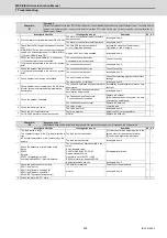
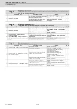
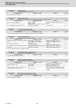
Warning No.
A3
In initial setup of ABS position
When the encoder with distance-coded reference marks is used, this warning is issued until the axis reaches the reference
position during the initial setup of the distance-coded reference check function. This warning disappears after the axis has
reached the position.
Investigation details
Investigation results
Remedies
SV SP
1
Warning does not disappear.
Encoder with
distance-coded
reference marks
Stopped on the way to the
reference position.
Setup again.
◯
-
Warning No.
A4
Dual signal warning
An input was detected in the signal related to the dual signal.
Investigation details
Investigation results
Remedies
SV SP
1
Warning does not disappear.
In emergency stop state?
Cancel the emergency stop.
◯
◯
Warning No.
A6
Fan stop warning
A cooling fan built in the drive unit stopped.
Investigation details
Investigation results
Remedies
SV SP
1
Check the alarm No. "45" items.
◯
◯
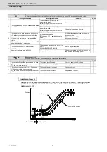
Warning No.
E0
Over regeneration warning
Over-regeneration detection level exceeded 80%.
Investigation details
Investigation results
Remedies
SV SP
1
Check the alarm No. "30" items.
◯
◯
Summary of Contents for MDS-E
Page 1: ......
Page 3: ......
Page 15: ......
Page 17: ......
Page 19: ......
Page 21: ......
Page 31: ......
Page 32: ...1 IB 1501229 F 1 Installation ...
Page 76: ...45 IB 1501229 F 2 Wiring and Connection ...
Page 132: ...101 IB 1501229 F 3 Safety Function ...
Page 142: ...111 IB 1501229 F 4 Setup ...
Page 277: ...MDS E EH Series Instruction Manual 4 Setup 246 IB 1501229 F ...
Page 278: ...247 IB 1501229 F 5 Servo Adjustment ...
Page 351: ...MDS E EH Series Instruction Manual 5 Servo Adjustment 320 IB 1501229 F ...
Page 352: ...321 IB 1501229 F 6 Spindle Adjustment ...
Page 404: ...373 IB 1501229 F 7 Troubleshooting ...
Page 455: ...MDS E EH Series Instruction Manual 7 Troubleshooting 424 IB 1501229 F ...
Page 456: ...425 IB 1501229 F 8 Maintenance ...
Page 475: ...MDS E EH Series Instruction Manual 8 Maintenance 444 IB 1501229 F ...
Page 476: ...445 IB 1501229 F 9 Power Backup System ...
Page 494: ...463 IB 1501229 F 10 Appx 1 Cable and Connector Assembly ...
Page 504: ...473 IB 1501229 F 11 Appx 2 D A Output Specifications for Drive Unit ...
Page 514: ...483 IB 1501229 F 12 Appx 3 Protection Function ...
Page 523: ...MDS E EH Series Instruction Manual 12 Appx 3 Protection Function 492 IB 1501229 F ...
Page 524: ...493 IB 1501229 F 13 Appx 4 Compliance to EC Directives ...
Page 528: ...497 IB 1501229 F 14 Appx 5 EMC Installation Guidelines ...
Page 540: ...509 IB 1501229 F 15 Appx 6 Higher Harmonic Suppression Measure Guidelines ...
Page 550: ......
Page 554: ......

