


MDS-E/EH Series Instruction Manual
7 Troubleshooting
419
IB-1501229-F
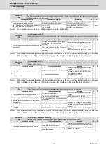
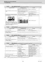
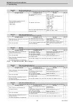
(2) Spindle parameter error No.
Error parameter
No.
Details
Related parameters
13017
The motor selected is of a motor series different from the drive unit's input voltage (200V/400V).
Or a motor of an incompatible motor series is selected.
SP017
13032
For the MDS-E/EH Series:
The power supply type (SP032) is set, but a power supply unit is not connected.
Always set the power supply type for the drive unit connected last on the NC optical communication cable.
SP032
For the MDS-EM/EMH Series:
Set SP032 to 0019
(
normal setting), or 0059 (external emergency stop function).
For the MDS-EJ/EJH Series:
The selected regenerative resistor is not supported in the drive unit of this capacity.
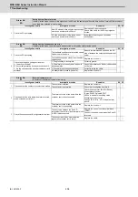
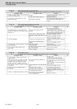
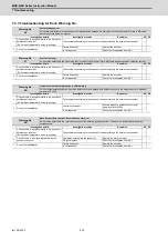
13097
-The expansion sub side encoder resolution (SP097) is set to "0" for an encoder that requires the resolution
expansion setting.
If the upper 16 bits for the encoder resolution are "0", this should be set to "-1".
-The expansion sub side encoder resolution (SP097) is set to a value other than "0" for an encoder that does
not support the resolution expansion setting.
SP019,SP031,SP097
13098
-The expansion main side encoder resolution (SP098) is set to "0" for an encoder that requires the resolution
expansion setting.
If the upper 16 bits for the encoder resolution are 0, this should be set to "-1".
-The expansion main side encoder resolution (SP098) is set to a value other than "0" for an encoder that
does not support the resolution expansion setting.
SP020,SP031,SP098
13125
When the DC excitation mode (SP225/bit4) is set, the initial DC excitation level (SP125) is set to a value
outside the setting range.
SP225, SP125
13126
When the DC excitation mode (SP225/bit4) is set, the final DC excitation level (SP126) is set to a value
outside the setting range.
SP225, SP126
13127
When the DC excitation mode (SP225/bit4) is set, the initial DC time (SP127) is set to a value outside the
setting range.
SP225, SP127
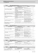
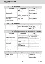
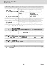
13142
-The pulse application time for an IPM spindle motor is excessive. Set the pulse application time (SP142) to
a value lower than 350
μ
s.
-The coil switch function is disabled and the pulse application coil for an IPM spindle motor is set to the low-
speed coil. Set the pulse application coil to the high-speed coil, or enable the coil switch function.
SP017,SP018,SP142,
SP226
13225
The DC excitation mode (SP225/bit4) has been set before the axis passes the Z phase. Set the DC excitation
mode after the axis passes the Z phase.
SP225
13238
The safety observation safety speed (SP238) and the safety observation safety motor speed (SP239) do not
satisfy the following equation:
(Round down the first decimal place. When the calculation results in "0", set SP239 to 1.
)
SP238,SP239
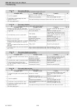
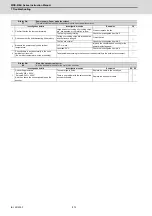
13239
The safety observation safety motor speed calculated from the actual gear ratio exceeds the overspeed
detection motor speed.
(Note) The safety observation safety motor speed calculated from the actual gear ratio
= SP238:SSCFEED / 360 × PC2 / PC1
PC2: Spindle side gear ratio (SP057 to SP060)
PC1: Motor side gear ratio (SP061 to SP064)
SP239
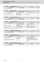
13255
The following settings are overflowing:
-Electronic gear and motor side gear
-Position loop gain
-Conversion from the speed detection unit to position detection unit
SP057 to SP060
SP061 to SP064
SP001 to SP003
SP019, SP020
SP057 : GRA1
SP061 : GRB1
SP239 : SSCRPM
360
×
=
SP238 : SSCFEED
Summary of Contents for MDS-E
Page 1: ......
Page 3: ......
Page 15: ......
Page 17: ......
Page 19: ......
Page 21: ......
Page 31: ......
Page 32: ...1 IB 1501229 F 1 Installation ...
Page 76: ...45 IB 1501229 F 2 Wiring and Connection ...
Page 132: ...101 IB 1501229 F 3 Safety Function ...
Page 142: ...111 IB 1501229 F 4 Setup ...
Page 277: ...MDS E EH Series Instruction Manual 4 Setup 246 IB 1501229 F ...
Page 278: ...247 IB 1501229 F 5 Servo Adjustment ...
Page 351: ...MDS E EH Series Instruction Manual 5 Servo Adjustment 320 IB 1501229 F ...
Page 352: ...321 IB 1501229 F 6 Spindle Adjustment ...
Page 404: ...373 IB 1501229 F 7 Troubleshooting ...
Page 455: ...MDS E EH Series Instruction Manual 7 Troubleshooting 424 IB 1501229 F ...
Page 456: ...425 IB 1501229 F 8 Maintenance ...
Page 475: ...MDS E EH Series Instruction Manual 8 Maintenance 444 IB 1501229 F ...
Page 476: ...445 IB 1501229 F 9 Power Backup System ...
Page 494: ...463 IB 1501229 F 10 Appx 1 Cable and Connector Assembly ...
Page 504: ...473 IB 1501229 F 11 Appx 2 D A Output Specifications for Drive Unit ...
Page 514: ...483 IB 1501229 F 12 Appx 3 Protection Function ...
Page 523: ...MDS E EH Series Instruction Manual 12 Appx 3 Protection Function 492 IB 1501229 F ...
Page 524: ...493 IB 1501229 F 13 Appx 4 Compliance to EC Directives ...
Page 528: ...497 IB 1501229 F 14 Appx 5 EMC Installation Guidelines ...
Page 540: ...509 IB 1501229 F 15 Appx 6 Higher Harmonic Suppression Measure Guidelines ...
Page 550: ......
Page 554: ......


