MDS-E/EH Series Instruction Manual
7 Troubleshooting
420
IB-1501229-F
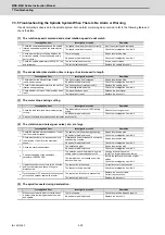
7.3.5 Troubleshooting the Spindle System When There Is No Alarm or Warning
If an abnormality is observed in the spindle system but no alarm or warning has occurred, refer to the following table and
check the state.
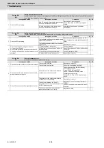
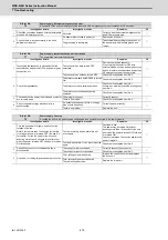
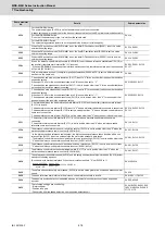
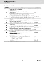
[1] The rotation speed command and actual rotation speed do not match.
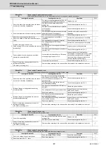
[2] The acceleration/deceleration time is long or has increased in length.
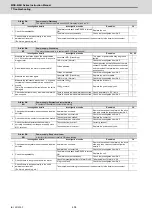
[3] The motor stops during cutting.
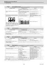
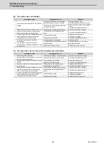
[4] The vibration and noise (gear noise), etc., are large.
[5] The spindle coasts during deceleration.
Investigation item
Investigation results
Remedies
1
Check the commanded speed and the spindle
rotation speed displayed on the drive monitor
screen.
The speed command is not input correctly.
Input the correct speed command.
The speed command is correct.
Check the investigation item No. 2.
2
Check whether there is slipping between the
motor and spindle. (When connected with a
belt or clutch.)
There is slipping.
Repair the machine side.
No particular problems found.
Check the investigation item No. 3.
3
Check the spindle parameters (SP026, SP129
and following).
The correct values are not set.
Set the correct values.
The correct values are set.
Replace the spindle drive unit.
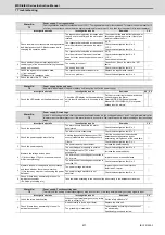
Investigation item
Investigation results
Remedies
1
Check whether the friction torque or load
inertia has increased.
The friction torque has increased.
Repair the machine side.
No particular problems found.
Check the investigation item No. 2.
2
Check if there is any abnormality in the motor's
rotation during coasting.
The bearings do not rotate smoothly.
Replace the spindle motor.
The bearings rotate smoothly.
Check the investigation item No. 3.
3
Check whether the torque limit signal has been
input.
The signal has been input.
Release the input signal.
The signal is not input.
Replace the drive unit.
Investigation item
Investigation results
Remedies
1
Check the load rate (load meter value) during
cutting.
The load meter sways over 120% during
cutting.
Reduce the cutting amount.
No particular problems found.
Check the investigation item No. 2.
2
Carry out the same investigations and remedies as section (4).
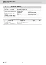
Investigation item
Investigation results
Remedies
1
Check the machine's dynamic balance. (Coast
from the maximum speed.)
The same noise is heard during coasting.
Repair the machine side.
No particular problems found.
Check the investigation item No. 2.
2
Check whether there is a resonance point in
the machine. (Coast from the maximum
speed.)
Vibration and noise increase at a set rotation
speed during coasting.
Repair the machine side.
No particular problems found.
Check the investigation item No. 3.
3
Check the machine's backlash.
The backlash is great.
Repair the machine side.
No particular problems found.
Check the investigation item No. 4.
4
Change the setting of the speed loop
parameter (SP005:VGN1).
The vibration and noise are lost when the
setting value is lowered by approx.100.
Change to the setting value.
(Note) The impact response will drop.
The symptoms do not change even if the
above value is set.
Return the setting values to the original
values.
Check the investigation item No. 5.
5
Jiggle the encoder connectors (drive unit side
and encoder side) and check if they are
disconnected.
The connection is loosened.
Correctly connect the connector.
The connector fixing is normal.
Check the investigation item No. 6.
6
Turn the power OFF, and check the connection
of the speed encoder cable with a tester.
The connection is faulty or disconnected.
Replace the encoder cable.
Correct the connection.
The connection is normal.
Replace the drive unit.
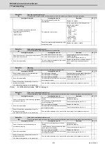
Investigation item
Investigation results
Remedies
1
When connected with a belt or clutch, check
whether there is slipping between the motor
and spindle.
There is slipping.
Check the machine side and repair it.
No particular problems found.
Replace the drive unit.
Summary of Contents for MDS-E
Page 1: ......
Page 3: ......
Page 15: ......
Page 17: ......
Page 19: ......
Page 21: ......
Page 31: ......
Page 32: ...1 IB 1501229 F 1 Installation ...
Page 76: ...45 IB 1501229 F 2 Wiring and Connection ...
Page 132: ...101 IB 1501229 F 3 Safety Function ...
Page 142: ...111 IB 1501229 F 4 Setup ...
Page 277: ...MDS E EH Series Instruction Manual 4 Setup 246 IB 1501229 F ...
Page 278: ...247 IB 1501229 F 5 Servo Adjustment ...
Page 351: ...MDS E EH Series Instruction Manual 5 Servo Adjustment 320 IB 1501229 F ...
Page 352: ...321 IB 1501229 F 6 Spindle Adjustment ...
Page 404: ...373 IB 1501229 F 7 Troubleshooting ...
Page 455: ...MDS E EH Series Instruction Manual 7 Troubleshooting 424 IB 1501229 F ...
Page 456: ...425 IB 1501229 F 8 Maintenance ...
Page 475: ...MDS E EH Series Instruction Manual 8 Maintenance 444 IB 1501229 F ...
Page 476: ...445 IB 1501229 F 9 Power Backup System ...
Page 494: ...463 IB 1501229 F 10 Appx 1 Cable and Connector Assembly ...
Page 504: ...473 IB 1501229 F 11 Appx 2 D A Output Specifications for Drive Unit ...
Page 514: ...483 IB 1501229 F 12 Appx 3 Protection Function ...
Page 523: ...MDS E EH Series Instruction Manual 12 Appx 3 Protection Function 492 IB 1501229 F ...
Page 524: ...493 IB 1501229 F 13 Appx 4 Compliance to EC Directives ...
Page 528: ...497 IB 1501229 F 14 Appx 5 EMC Installation Guidelines ...
Page 540: ...509 IB 1501229 F 15 Appx 6 Higher Harmonic Suppression Measure Guidelines ...
Page 550: ......
Page 554: ......

