
MDS-E/EH Series Instruction Manual
1 Installation
15
IB-1501229-F
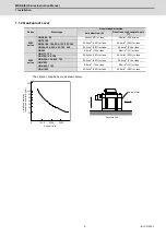
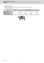
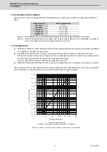
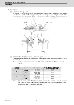
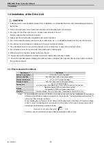
1.2.3 Shaft Characteristics
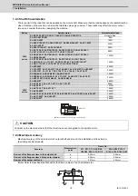
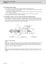
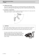
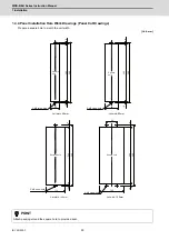
There is a limit to the load that can be applied on the motor shaft. Make sure that the load applied on the radial direction,
when mounted on the machine, is below the tolerable values given below. These loads may affect the motor output
torque, so consider them when designing the machine.
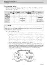
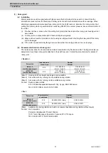
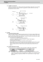
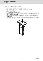
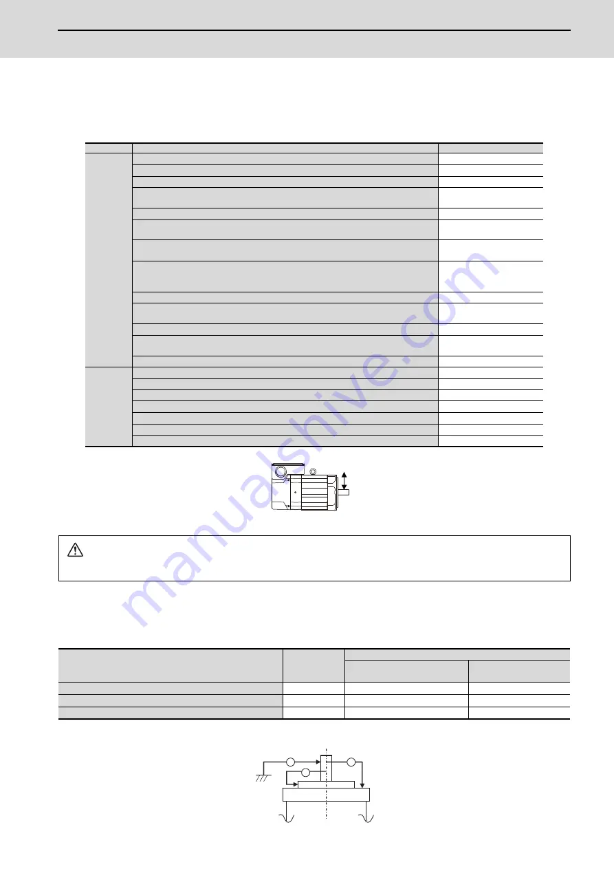
1.2.4 Machine Accuracy
Machine accuracy of the spindle motor's output shaft and around the installation part is as below.
(Excluding special products)
(Note) Refer to Specifications Manual for the frame number of each spindle motor.
Series
Spindle motor
Tolerable radial load
200V
series
SJ-D5.5/120-02T-S, SJ-DL3.7/240-01T, SJ-DL5.5/200-01T-S
Not permitted
SJ-VL11-05FZT-S01
98N
SJ-VL2.2-02ZT
196N
SJ-DL5.5/150-01T, SJ-DL5.5/200-01T, SJ-DL5.5/240-05T, SJ-V3.7-02ZT,
SJ-VL11-02FZT
245N
SJ-DL0.75/100-01T, SJ-DL1.5/100-01
490N
SJ-D3.7/100-01, SJ-D5.5/120-02, SJ-DJ5.5/100-01, SJ-DJ5.5/120-01,
SJ-DL7.5/150-01T, SJ-V2.2-01T, SJ-DG3.7/120-03T
980N
SJ-D5.5/100-01, SJ-D5.5/120-01, SJ-DJ7.5/100-01, SJ-DJ7.5/120-01,
SJ-DG5.5/120-04T
1470N
SJ-D7.5/100-01, SJ-D7.5/120-01, SJ-D11/100-01, SJ-DJ11/100-01,
SJ-DJ15/80-01, SJ-V11-01T, SJ-DG7.5/120-05T, SJ-DG11/100-03T,
SJ-DG11/120-03T, SJ-DG15/120-02T-K, SJ-DN7.5/80-01
1960N
SJ-V22-06ZT
2450N
SJ-V15-09ZT, SJ-V18.5-01ZT, SJ-V18.5-04ZT, SJ-V22-01ZT, SJ-V22-04ZT,
SJ-V26-01ZT, SJ-V11-09T, SJ-V15-03T, SJ-V18.5-03T, SJ-V22-05T
2940N
SJ-D15/80-01, SJ-D18.5/80-01, SJ-DN11/80-01
3430N
SJ-D22/80-01, SJ-D26/80-01, SJ-V37-01ZT, SJ-V45-01ZT, SJ-V22-09T,
SJ-VK22-19ZT, SJ-DN15/80-01, SJ-DN18.5/80-01
3920N
SJ-V55-01ZT
5880N
400V
series
SJ-4-V2.2-03T, SJ-4-V3.7-03T, SJ-4-V7.5-13ZT
980N
SJ-4-V5.5-07T
1470N
SJ-4-V7.5-12T, SJ-4-V11-18T
1960N
SJ-4-V26-08ZT
2450N
SJ-4-V18.5-14T, SJ-4-V22-15T, SJ-4-V22-18ZT, SJ-4-V15-20T, SJ-4-V22-16T
2940N
SJ-4-V37-04ZT, SJ-4-V45-02T
3920N
SJ-4-V55-03T
5880N
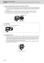
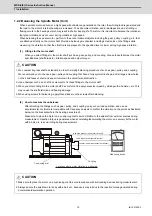
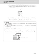
CAUTION
Consider on the machine side so that the thrust loads are not applied to the spindle motor.
Accuracy
Measurement
point
Frame No.
A71, B71, C71, A90, B90,
C90,D90, E90, A112, B112
A160, B160, C160,
D160, A180, B180, A225
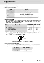
Run-out of the flange surface to the output shaft
a
0.03mm
0.05mm
Run-out of the flange surface's fitting outer diameter
b
0.02mm
0.04mm
Run-out of the output shaft end
c
0.01mm
0.02mm
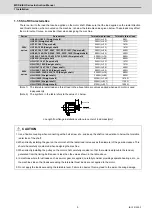
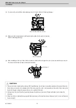
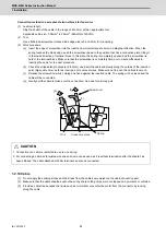
Radial load
(Note)
The load point is at the one-half of the shaft length.
a
c
b
Summary of Contents for MDS-E
Page 1: ......
Page 3: ......
Page 15: ......
Page 17: ......
Page 19: ......
Page 21: ......
Page 31: ......
Page 32: ...1 IB 1501229 F 1 Installation ...
Page 76: ...45 IB 1501229 F 2 Wiring and Connection ...
Page 132: ...101 IB 1501229 F 3 Safety Function ...
Page 142: ...111 IB 1501229 F 4 Setup ...
Page 277: ...MDS E EH Series Instruction Manual 4 Setup 246 IB 1501229 F ...
Page 278: ...247 IB 1501229 F 5 Servo Adjustment ...
Page 351: ...MDS E EH Series Instruction Manual 5 Servo Adjustment 320 IB 1501229 F ...
Page 352: ...321 IB 1501229 F 6 Spindle Adjustment ...
Page 404: ...373 IB 1501229 F 7 Troubleshooting ...
Page 455: ...MDS E EH Series Instruction Manual 7 Troubleshooting 424 IB 1501229 F ...
Page 456: ...425 IB 1501229 F 8 Maintenance ...
Page 475: ...MDS E EH Series Instruction Manual 8 Maintenance 444 IB 1501229 F ...
Page 476: ...445 IB 1501229 F 9 Power Backup System ...
Page 494: ...463 IB 1501229 F 10 Appx 1 Cable and Connector Assembly ...
Page 504: ...473 IB 1501229 F 11 Appx 2 D A Output Specifications for Drive Unit ...
Page 514: ...483 IB 1501229 F 12 Appx 3 Protection Function ...
Page 523: ...MDS E EH Series Instruction Manual 12 Appx 3 Protection Function 492 IB 1501229 F ...
Page 524: ...493 IB 1501229 F 13 Appx 4 Compliance to EC Directives ...
Page 528: ...497 IB 1501229 F 14 Appx 5 EMC Installation Guidelines ...
Page 540: ...509 IB 1501229 F 15 Appx 6 Higher Harmonic Suppression Measure Guidelines ...
Page 550: ......
Page 554: ......


